A level reading alone does not start a pump, close a valve or prevent an overflow. You need to match the tank duty, sensing method, switching logic, actuator and protective functions so the system responds correctly at both normal and abnormal levels.
Key takeaways
- A controller converts measured tank level into pump, valve or flow action.
- Set separate low-level and high-level responses before selecting hardware.
- Match the sensing method to liquid properties, temperature and tank geometry.
- Specify control logic, alarm points, outputs and installation conditions upfront.
What a liquid level controller does in a tank
A liquid level controller turns a tank’s level condition into an action: start or stop a pump, open or close a valve, or adjust flow to keep the process within limits. It is the decision-making part of a level-control loop, not merely the device that detects liquid.
| Role | What it does |
|---|---|
| Level sensor | Detects a physical condition, such as float position, conductivity, capacitance or radar reflection |
| Point-level switch | Reports that liquid has reached one chosen elevation |
| Level transmitter | Reports a continuous level value, such as 0–100% or 4–20 mA |
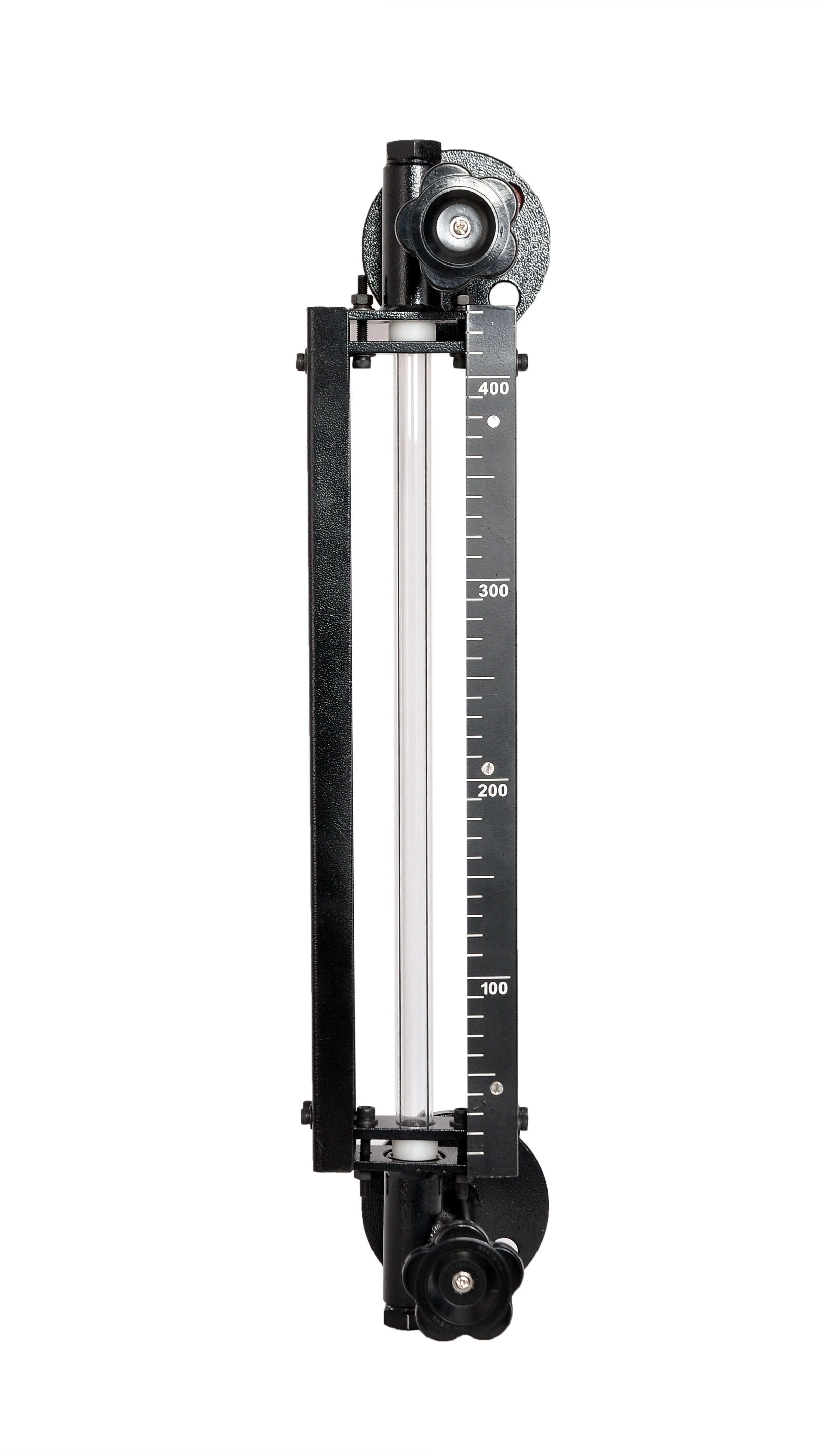
| Level indicator | Displays the measured level locally |
| Liquid level controller | Compares the condition with setpoints and commands an actuator |
| Pump control panel | Supplies switching, protection and manual controls for a pump; it is not automatically a level controller |
The main liquid level controller applications are:
- Filling a receiving tank by opening an inlet valve or starting a feed pump at low level.
- Transferring liquid by controlling an outlet pump or valve between storage vessels.
- Draining a vessel while preventing the discharge pump from running below its safe level.
- Preventing overflow with a high-level command, alarm or independent high-high shutdown.
- Protecting a pump from dry running, vortexing or gas entrainment with a low-level trip.
- Batching a measured quantity by stopping transfer at a calibrated level.
- Maintaining a working level with on/off control or continuous valve or pump adjustment.
On/off control uses separate start and stop elevations, called hysteresis or deadband, to prevent rapid cycling. A transmitter that only displays level reports information; it does not create closed-loop control without a controller and final control element.
How the tank level control loop responds at low and high levels
At the low level, the controller starts an inlet pump or opens an inlet valve; at the high level, it stops filling or starts discharge. The liquid level control system components form a loop: sensing element or transmitter, controller or relay, power supply, wiring, actuator, feedback, alarm, manual override and isolation valves or switches.
- The sensing element measures level, or a point switch detects a low or high elevation. The signal travels through wiring to a relay, PLC or controller.
- At the low start point, the controller energises a pump starter or valve actuator. An alarm can announce low level, while an independent low-low switch can stop a pump for dry-run protection.
- As level rises to the higher stop point, the controller de-energises filling or starts an outlet pump or discharge valve. The actuator’s feedback confirms its position or running state.
- Use the manual override only under a defined operating procedure, and isolate power, instrument air or process lines before maintenance. Specify the safe response to signal or power loss.
| Control arrangement | Response | Best fit |
|---|---|---|
| On/off pump control | Switches at separated start and stop levels | Filling or transfer with a pump starter |
| Measurement-only transmission | Sends level to an indicator, PLC or control room without commanding equipment | Monitoring, records or a separate operator decision |
| Continuous control | Modulates a valve or variable-speed pump from transmitter feedback | Stable working level or changing process demand |
Hysteresis, also called deadband, separates the low start point from the high stop point. One switching level makes a pump chatter: turbulence crosses the threshold, the motor starts, level shifts, and the motor immediately stops, rapidly wearing contacts and equipment.
Choosing the sensing method for the tank and liquid
Choose the sensing method around the liquid, tank geometry and control task—not around the controller alone. Tank level controller applications use point detection for pump start/stop or overflow alarms, and continuous measurement for modulating valves, batching and working-level control.
| Option | Best fit | Main limitations |
|---|---|---|
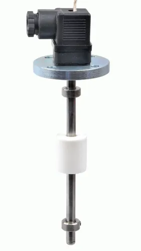
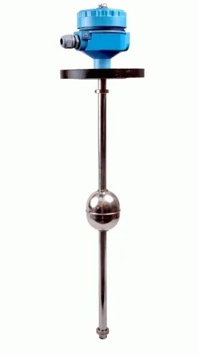
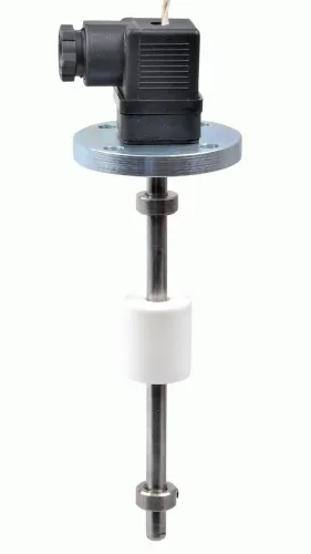
| Float switch | Simple on/off control in clean, low-to-moderate viscosity liquids | Needs room to move; turbulence, solids and deposits can jam it |
| Side-mounted point switch | High or low alarm where a nozzle is available | Detects one elevation; viscosity, coating and mounting orientation affect response |
| Continuous transmitter | Modulating control and level indication | Needs a representative mounting location and correct range |
| Hydrostatic sensor | Open tanks with stable liquid density | Density changes alter the reading; closed tanks require vapor-pressure compensation |
| Capacitance probe | Conductive or non-conductive liquids, including compact vessels | Coating, changing dielectric constant and suspended solids can shift the switching point |
| Ultrasonic transmitter | Non-contact measurement in calm, open-path tanks | Foam, condensation, vapor, turbulence, temperature, agitators and obstructions weaken or distort echoes |
For closed, hot, pressurised or corrosive tanks, radar avoids liquid contact. Check foam, buildup, false echoes, nozzle geometry and internal obstructions; a stilling well or guided-wave radar can improve the path but adds a surface that can foul or block. Guided-wave radar suits difficult vapour spaces and some interface duties.
Hydrostatic measurement also depends on vapor-space pressure in a closed tank, not only liquid height. For two liquids, select a method that detects their boundary—such as differential pressure, displacer, capacitance, guided-wave radar or radiometric measurement—because total level alone cannot reveal an accumulating heavy or light phase.
Verify wetted materials, temperature, pressure and hazardous-area classification before installation.
Matching the controller architecture to the tank duty
Match the controller architecture to the tank duty: liquid level controller applications differ between receiving, supply, buffer and storage tanks. The manipulated variable may be an inlet valve, outlet valve, transfer pump, bypass valve or recirculation valve.
1. For a one-pump tank, use the level controller to modulate the inlet or outlet, or start and stop the pump between separate levels. Add hysteresis or the pump will chatter near one setpoint.
2. For duty/standby pumps, assign automatic alternation and start the standby pump on a defined failure or high-demand condition. Confirm that each pump has low-low protection.
3. For multiple tanks, give each tank its own measurement, control function and permissives. Coordinate transfers through a PLC or DCS so one tank cannot overflow while another pump runs dry.
4. For a receiving tank, control the inlet valve or feed pump. For a supply tank, control the outlet valve or discharge pump. Use bypass or recirculation when changing the main process flow would disturb another operation.
5. For a buffer tank, tune the level loop slowly. A fast loop passes upstream flow disturbances downstream instead of absorbing them.
Normal control is separate from protective action. Use an independent low-low switch to stop a pump or close an outlet when exposing equipment creates danger, and an independent high-high switch to stop filling or close an inlet.
For petroleum storage tanks, API Standard 2350 treats automated overfill prevention as an independent protection layer rather than routine gauging or control.
Choose fail-open or fail-closed from the hazard and the consequence of lost power, instrument air, signal or output. The safe response may be different for an inlet valve, outlet valve and pump.
What to specify before installing a tank level controller
Before installing a tank level controller, specify the liquid level control system components, their electrical limits and their safe response to faults.
| Item | Specify or inspect | Commissioning check |
|---|---|---|
| Switching and power | Switching current, motor inrush, relay contact rating and control voltage; add a contactor and overload relay when the controller cannot switch the motor directly | Confirm the overload setting, phase protection and contactor operation |
| Wiring and enclosure | Maximum cable length, conductor size, gland arrangement and ingress protection rating, such as IP65 or IP66 | Test insulation, continuity, earthing and every isolation point |
| Control actions | High and low operating setpoints, separate high-high and low-low trips, hysteresis, manual mode and actuator fail position | Verify pump or valve feedback, start, stop and recovery after power or signal loss |
Check the nozzle location against the inlet, agitator, heating coil, ladder and internal supports. Turbulence, splashing, false echoes or a blocked probe can make a correctly configured controller respond to a level that does not represent the bulk liquid.
- Test each alarm at its actual setpoint and confirm the displayed tag and operator response.
- Simulate low-low and high-high conditions independently; do not treat either trip as an ordinary control alarm.
- Run automatic and manual modes, then remove power or signal to confirm the specified fail position.
- Record start, stop, alarm, trip and recovery behaviour.
Filpro Sensors Pvt Ltd can help compare float, point-switch and continuous-transmitter arrangements, but choose from the liquid, duty, geometry and hazard—not the device label.
Related products
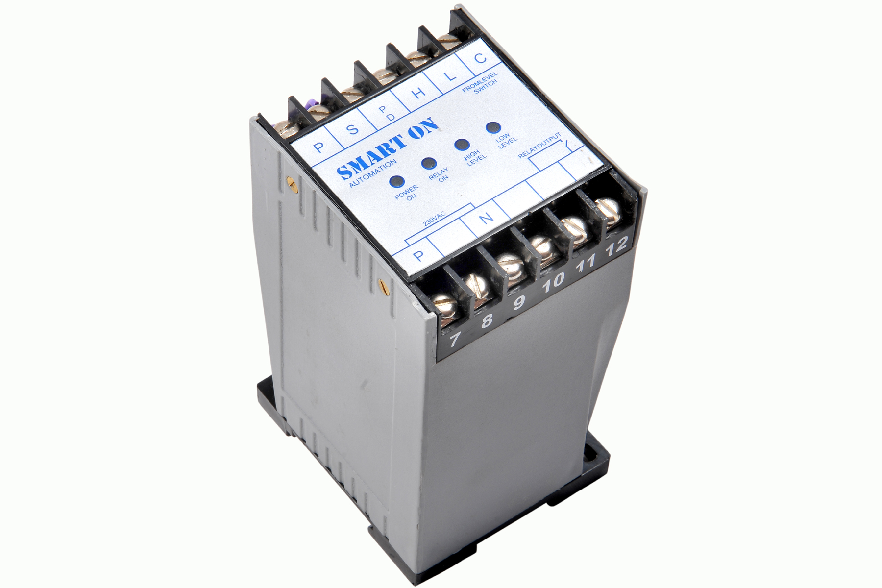 | Controller Filpro Sensors Pvt Ltd manufactures industrial Level Controller (Smart On) to automatically start & stop the pump. View product → |
 | Level Switch Filpro offers most reliable, cost effective Side Mounted Level Switch for point level sensing. View product → |
Related products
 | Level Transmitter Float Level Transmitters Are Ideal For Continuous Level Monitoring In Water, Diesel, Chemical And Oils For Accurate Level Measurement. View product → |
 | Level Transmitter Hydrostatic liquid level transducers and transmitters with flush diaphragm is designed fora wide variety of level measurement applications. View product → |
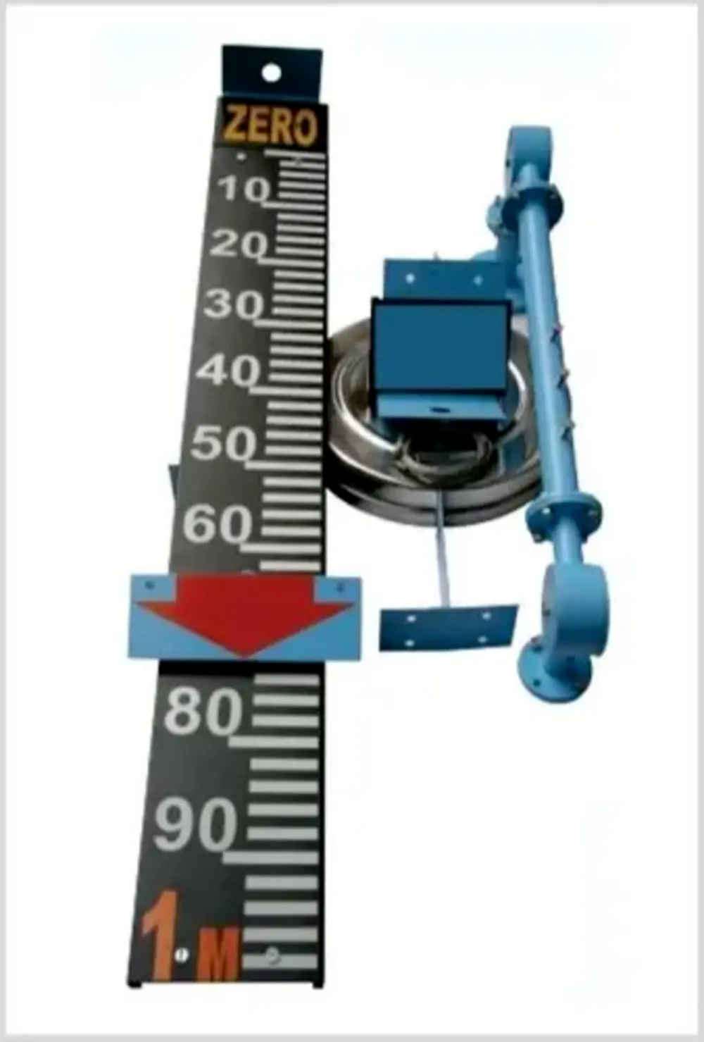 | Level Indicator The Float & Board Level Indicators consists of a float connected to a pointerthrough a rope via a set of pulleys. View product → |
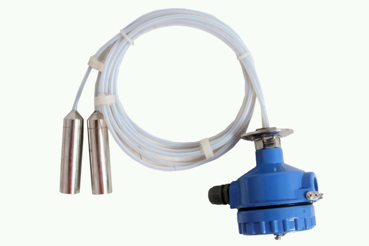 | Level Transmitter can be used for conductive as well as non conductive liquids. View product → |