A probe lowered into a well does not measure water height directly; it measures the pressure created by the water above its sensing diaphragm. By the end, you will be able to select the pressure reference and range, install and wire the probe correctly, and convert its output into water level, depth and usable volume.
Key takeaways
- Use hydrostatic pressure and liquid density to calculate water height.
- Choose a pressure range above maximum water depth without sacrificing resolution.
- Keep the vented cable dry, protected and free from sharp bends.
- Calibrate the signal against well reference points before calculating volume.
How pressure at the diaphragm becomes water level
A submersible level transmitter for wells measures hydrostatic pressure at its sensing diaphragm: the deeper the diaphragm sits, the greater the liquid weight pressing on it. The transmitter converts that pressure to height with h = P/(ρg), where h is liquid height, P is pressure, ρ is liquid density, and g is gravitational acceleration.
Fresh water near room temperature produces about 9.8 kPa (1.42 psi) for each metre of depth. That conversion is not universal.
Check the liquid density when the well contains:
- Brine
- Chemicals
- Sludge
- Water at a materially different temperature
A denser liquid produces more pressure at the same height, so a fresh-water calibration will indicate a level that is too high.
| Pressure reference | What the transmitter compares | Meaning in an open well |
|---|---|---|
| Gauge | Liquid pressure against atmospheric pressure | Normal choice; atmospheric changes cancel |
| Absolute | Liquid pressure against a vacuum reference | Barometric changes appear as false level changes |
| Sealed gauge | Liquid pressure against a sealed reference pressure | Barometric effects are reduced, but the sealed reference can shift with temperature or age |
A vented gauge transmitter uses a cable with electrical conductors and an atmospheric reference tube. Keep that tube open, dry, kink-free, and protected from mud and insects; a blocked or flooded vent causes offset or slow response.
Flow and pump turbulence also reach the diaphragm, so a clean stilling tube or calm mounting point can steady the reading without trapping sediment.
What the probe needs from its well installation
Position the probe from a surveyed reference point, lowering it until the diaphragm is below the lowest measured level. Face it downward; keep it clear of the bottom, pump, screen and casing. Contact causes error or damage.
Suspend it from the rated cable or separate support, not an overloaded cable gland. Protect the cable from abrasion. If pumping turbulence makes readings jump, use a stilling tube or calm section that neither traps sediment nor isolates the sensor from well level.
A vent tube is part of the measurement system. In a vented submersible transmitter installation, keep it open to atmosphere and protect it from water, condensation, insects, mud and kinks. Blockage or flooding causes offset, slow response or barometric error. Preserve the vent path and water-tight integrity during splicing or extension.
Pumping changes hydrostatic pressure in a well: drawdown lowers the level near the pump, while recovery raises it after shutdown. Choose the reading needed:
| Reading | Meaning | Use |
|---|---|---|
| Instantaneous | Current dynamic level; responds to turbulence | Immediate control or alarm |
| Filtered | Smoothed signal; suppresses short fluctuations | Routine control |
| Stabilized | Level after pumping stops and recovery | Static-level comparison |
- Check for biofilm, iron, sand or oil fouling; fit a protective cage without blocking pressure access.
- Clean gently: avoid scraping the diaphragm, pressure jets and incompatible solvents.
- Confirm wetted-material compatibility with the water chemistry. An IP68 marking still requires checking the manufacturer-declared immersion depth and duration.
How to choose range, output and receiving equipment
Begin submersible level transmitter range selection with the maximum expected water depth, convert that head to pressure using the actual or worst-case density, and add allowance for surge, pumping conditions, and uncertainty in reference elevation or installation. Choose the smallest standard upper range that covers that total.
Too small causes over-range or permanent damage; too large spreads the signal across more pressure and reduces usable resolution.
| Output | Equipment needed | Selection checks |
|---|---|---|
| 4–20 mA | Loop supply, receiver, and wiring | Confirm allowable loop resistance at the minimum supply voltage; a 4–20 mA well level transmitter suits long runs and industrial inputs. |
| Voltage | Stable supply and voltage input | Check input impedance, cable voltage drop, grounding, and the receiver’s permitted voltage range. |
| Digital | Compatible power, protocol, and configuration software | Confirm protocol support, addressing, communications wiring, and software access before installation. |
Output type does not determine total accuracy. Check density assumptions, zero or reference elevation, cable resistance, supply-voltage limits, electromagnetic interference, and receiver scaling; scale the selected pressure range to the intended level range and engineering units.
Before ordering, ask whether:
- The diaphragm material tolerates the well water’s chloride concentration and chemistry.
- The diaphragm seal and elastomer are compatible with aggressive contaminants.
- The cable jacket withstands that water and the installation environment.
- The manufacturer has verified the complete wetted assembly, not just the steel body.
How to wire, protect and commission the transmitter
Make submersible transmitter wiring match the manufacturer’s conductor and vent-tube arrangement. Verify polarity, use the specified supply voltage, and confirm that the receiver accepts the transmitter’s output type, such as 4–20 mA, with the correct pressure-to-level scaling and engineering units.
Bond and ground the control panel, well casing and nearby site equipment according to the site electrical design. Keep protective bonding separate from the signal return unless the manufacturer’s wiring diagram permits that connection; an unintended parallel path can introduce loop current and a false level.
Install surge protection at the control panel and at the signal entry where the cable enters the building or cabinet. Long cables, conductive water and metal casings can carry lightning transients into the transmitter, even when its enclosure is rated for immersion.
A vented cable splice must preserve the atmospheric reference tube, shielding arrangement and water ingress protection. Keep the tube open to clean, dry atmosphere; a blocked or flooded tube defeats pressure compensation and causes offset, slow response or barometric error.
For well level transmitter commissioning, complete this sequence before immersion:
- Power the probe and check its zero or ambient reading.
- Compare the displayed output with the expected range.
- Inspect the cable for cuts, crushed sections and kinks.
- Record the reference elevation.
Check the installed reading against these conditions:
| Condition | Expected result | Investigate if |
|---|---|---|
| Static water | Stable, plausible level | Offset or drift |
| Pumping | Reading changes in the correct direction | No response or erratic output |
| Recovery | Reading returns toward the static value | Persistent error or hysteresis |
How to turn the signal into depth, level and volume
Turn the signal into depth by defining the datum and measurement direction before calculating. The datum is the surveyed reference elevation, sensor elevation is the diaphragm’s elevation, and water-surface elevation is the surface relative to that datum. Measure upward from the sensor to the surface; measure depth to water downward from the datum.
1. Scale a 4–20 mA output from the transmitter’s configured pressure range, not an assumed range: P = Pmin + (I − 4)/16 × (Pmax − Pmin). This gives pressure P in the selected units; receiving-instrument scaling must match it.
2. For the water level calculation from pressure, calculate water head h = P/(ρg). With P = 9.8 kPa, fresh water density ρ ≈ 1,000 kg/m³ and g = 9.81 m/s², h ≈ 1.0 m.
3. When the diaphragm is below the surface, water-surface elevation = sensor elevation + h. Then depth to water from transmitter output = datum elevation − water-surface elevation. A zero-elevation error shifts every result.
4. For volume, use surveyed geometry. A cylindrical section uses V = πr²h. An irregular well needs a depth-to-volume table or survey curve, with separate sections for casing, sump and changing diameter.
Use the actual liquid density: a density error changes calculated head. Pump drawdown lowers the dynamic level near the probe, while recovery or a remote static measurement can show a higher level; decide whether control needs instantaneous, stabilized or filtered level.
How to specify a submersible level transmitter for wells that will work in service
Treat the well level transmitter specification as a service document, not a catalogue request. Ask the supplier to confirm:
- Pressure reference type—vented gauge, sealed-gauge, or absolute—plus calibrated density, range, and overload limit.
- Diaphragm, seals, cable jacket, and protective-material compatibility with the well chemistry.
- Declared IPX8 test conditions, including immersion depth, duration, and cable-entry coverage.
- Cable length, vent arrangement, output wiring, supply range, and maximum loop resistance.
- Accuracy, temperature limits, calibration units, cleaning method, and recommended surge protection.
Use a vented gauge in an open well; use sealed-gauge only when its fixed reference and barometric error are acceptable, and absolute when barometric pressure must be retained or the well is sealed. In a pumping well, take a separate static-water reading to validate whether the transmitter shows drawdown or aquifer level.
Filpro Sensors Pvt Ltd can review depth, chemistry, pump behaviour, datum, output hardware, and protection instead of receiving a generic request for a submersible level transmitter for wells.
Related product
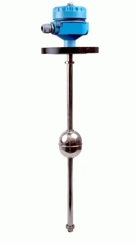
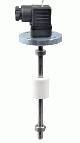
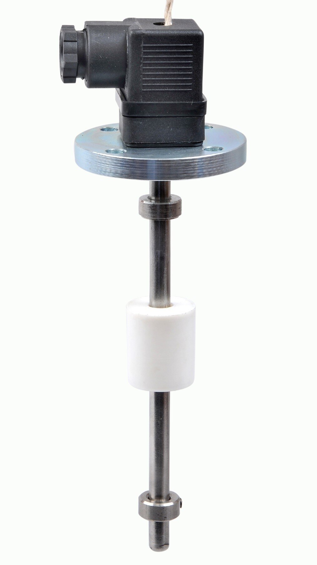
 | Level Transmitter Hydrostatic liquid level transducers and transmitters with flush diaphragm is designed fora wide variety of level measurement applications. View product → |
Frequently asked questions
How does a submersible level transmitter measure water level in a well?
It measures hydrostatic pressure at its diaphragm. Calculate water height with h = P/(ρg), using pressure, liquid density and gravitational acceleration.
What does a submersible level transmitter need from its well installation?
The probe needs a known reference elevation, sufficient clearance, strain relief, protection from impact and a cable route that keeps the vent tube dry.
How do you choose the transmitter range and output?
Select a range that covers the maximum water depth, then match the output—such as 4–20 mA—to the receiving equipment and cable distance.
How do you commission and protect a well level transmitter?
Wire the transmitter with the correct supply and polarity, protect the loop from surges and moisture, then compare readings with measured reference levels.
How do you convert a transmitter signal into depth, level and volume?
Scale the output to pressure, convert pressure to height using liquid density, reference height to the well datum, and apply the tank or well volume curve.