A correct selection starts with liquid head, not tank volume, diameter or maximum vessel pressure. By the end, you will be able to calculate the pressure span, set the lower and upper range values, account for density and installation offsets, and specify the checks that prevent false level readings.
Key takeaways
- Calculate hydrostatic span with 9.806 × specific gravity × height in metres.
- Set LRV and URV from actual operating levels, not total tank volume.
- Include wet-leg head, elevation offsets, pressure ratings and impulse-line details.
- Specify process connections, materials, accuracy, output and calibration range.
Calculate the hydrostatic pressure span from liquid height
Differential pressure level transmitter sizing begins with vertical liquid height, not tank volume. Calculate the hydrostatic head with ΔP = ρgh, where ρ is liquid density, g is gravitational acceleration, and h is the measured height. Using specific gravity, the practical formula is ΔP in kPa = 9.806 × SG × h in metres.
- Set h at the minimum operating level above the high-pressure tap to establish the lower-range value (LRV).
- Set h at the maximum operating level above that same tap to establish the upper-range value (URV).
- Subtract the LRV head from the URV head to obtain the transmitter span.
For example, a 0–3 m water measurement at SG 1.000 requires about 0–29.4 kPa, or 0–294 mbar. A 10 m liquid column at SG 0.1 produces only about 9.8 kPa, so selecting a much larger range for pressure-rating margin can reduce turndown and low-level accuracy.
Use the actual operating density. If SG changes during a batch, the transmitter can indicate a different level while the physical height stays constant; choose density compensation or another measurement technology when that error matters.
Tank shape does not alter the height-to-pressure relationship for a uniform liquid. It does affect volume, so a horizontal or irregular tank needs a separate level-to-volume strapping table.
In a closed tank, connect the high side to the bottom and the low side to the vapour space; in an open tank, keep the low side properly vented.
Set the LRV and URV from operating levels and specific gravity
For a differential pressure level transmitter tank, calibrate to the minimum and maximum operating levels, not the vessel’s full height. Set the LRV to the hydrostatic differential pressure at the minimum level and the URV to the pressure at the maximum level.
Calculate each endpoint with ΔP = ρgh, using the liquid’s SG and the vertical height above the transmitter’s pressure-tap datum. Do not force the LRV to zero unless zero level is the actual process reference.
Use these range-setting decisions:
- Select the design SG for the liquid at its operating temperature. A 10 m water column at SG 1.0 produces about 98 kPa; the same height at SG 0.1 produces about 9.8 kPa.
- If SG changes with temperature, concentration, composition or batch, one fixed calibration cannot show true level across that range. Add density compensation, update the calibration for each known SG, or choose another measurement technology.
- Set the URV high enough for the maximum credible DP, but do not select an unnecessarily large transmitter span to gain pressure-rating margin. That choice reduces turndown and low-level accuracy.
- Account separately for wet-leg or reference-leg head, static pressure rating, and one-sided overpressure during startup, shutdown and valve sequencing.
This is the central decision in differential pressure level transmitter sizing: choose a calibrated DP range that covers real operating levels at the stated SG, while checking pressure and process-connection ratings independently.
Account for closed tanks, open tanks, wet legs and elevation offsets
Installation arrangement changes the calibrated zero, not only the measured span. Size the differential pressure level transmitter range to include the pressure difference caused by the actual high- and low-side connection elevations; a correct liquid-level span can still require zero suppression or elevation specification.
- Open tank: Reference the low side to atmosphere through a clear, properly vented connection. Barometric changes then affect both the tank pressure and reference, leaving the liquid-head differential largely unchanged. A blocked vent creates a false level signal.
- Closed tank: Connect the high side to the bottom and the low side to the vapor space. Common vapor pressure cancels when both connections see the same pressure and the gas-side line contains no liquid column.
- Wet leg: The low-side fill-fluid column creates a fixed positive or negative zero offset. Set that offset from the leg height, fill-fluid density, and reference temperature; evaporation, condensation, freezing, or density change moves the zero.
- Dry leg: Condensate can gradually turn the reference line into an unintended wet leg, shifting zero as liquid accumulates.
For a pressurized differential pressure level transmitter tank, place the vapor-space connection where it remains representative of tank pressure and cannot flood from liquid carryover. If that connection floods intermittently, the instrument measures the difference between two liquid columns, producing abrupt errors that change with tank load.
The transmitter’s installed height therefore belongs in the range and zero calculation, even when the vessel’s operating level limits stay unchanged.
Check pressure ratings, accuracy and impulse-line installation
After calculating the hydrostatic span, verify pressure ratings, accuracy at the operating point, and impulse-line installation. Differential pressure level transmitter sizing is incomplete if it checks only the measured span.
- Confirm the calibrated differential-pressure range covers the required LRV and URV without excessive unused capacity. A very large range can reduce low-level resolution and worsen zero stability, calibration resolution, static-pressure effect, and temperature error. Rangeability does not replace accuracy.
- Check the transmitter’s static or line-pressure rating separately from its differential-pressure range. Also verify the flange and gasket pressure-temperature ratings, plus the one-sided overpressure rating for a blocked impulse line or sudden pressure imbalance. A transmitter can handle the DP span and still be unsafe at the tank’s internal pressure.
- Request accuracy figures across the calibrated range at the actual process temperature and static pressure, not only the headline reference accuracy. Include zero shift, temperature effect, static-pressure effect, and impulse-line contribution in the error budget.
- Route liquid-service impulse lines with continuous slope toward the transmitter or process connection so gas pockets cannot form. Route gas-service lines so condensate drains predictably. Trapped gas, unequal line temperatures, plugged strainers, leaks, and partly closed root valves create false level readings.
Before commissioning, inspect both lines for equal routing where required, full-open root valves, correct gaskets, leak tightness, and clear passages. Record the calibration and confirm the one-sided overpressure case has not shifted zero.
Turn the calculation into a complete transmitter specification
Turn differential pressure level transmitter sizing into a datasheet that another engineer can build from.
For a differential pressure level transmitter tank specification, state the liquid name, minimum and maximum operating levels, minimum and maximum specific gravity, operating and design temperature, vessel pressure and vacuum, measurement span, calibrated LRV and URV, output signal, process connections, wetted materials, electrical area classification, enclosure rating, and required accuracy.
Record whether density changes with temperature, concentration, composition or batch.
Include these practical details:
- State the normal and worst-case density, not only a nominal SG.
- Identify high- and low-side connection locations and the impulse-line or capillary arrangement.
- Specify flange size, diaphragm material, fill fluid, ambient temperature and capillary length when using remote seals.
- Define alarm points, display units, communication protocol and proof-test requirements.
Choose the measurement arrangement against the failure you need to avoid:
| Option | What it means | When it applies |
|---|---|---|
| Direct DP | Measures hydrostatic head through connected impulse lines | Use when density remains stable and connections stay clear |
| Density compensation | Corrects level using a density input or calculated process condition | Use when temperature, concentration or batches alter SG enough to create unacceptable level error |
| Remote seals | Isolates the transmitter with diaphragms and capillaries | Use for corrosive, hot, viscous, plugging or crystallising liquids; account for capillary temperature error |
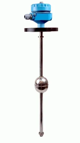
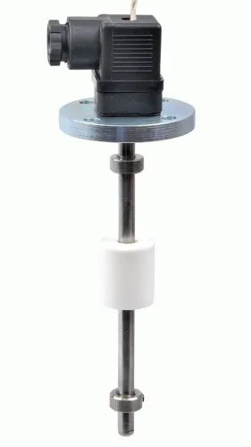
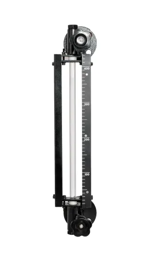
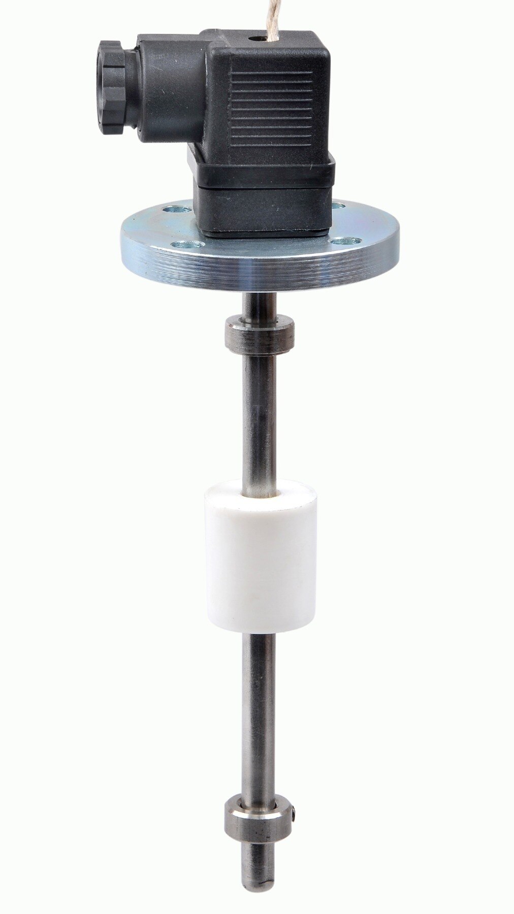
| Float or ultrasonic | Measures position or distance without relying on hydrostatic head | Choose when density varies unpredictably or impulse lines create more risk than they remove |
Filpro Sensors Pvt Ltd can help compare a hydrostatic specification with float or ultrasonic alternatives when density data is incomplete.
Frequently asked questions
How do you calculate the pressure span for a differential pressure level transmitter?
Use ΔP in kPa = 9.806 × specific gravity × liquid height in metres. The height is the vertical distance between the lower and upper measurement points.
How do you set the LRV and URV on a differential pressure level transmitter?
Calculate the differential pressure at the minimum operating level for the LRV and at the maximum operating level for the URV. Use the liquid’s specific gravity at operating conditions.
How do closed tanks, open tanks, wet legs and elevation affect transmitter sizing?
An open tank references atmospheric pressure, while a closed tank uses both high- and low-pressure connections. Include wet-leg liquid head and any elevation difference between the transmitter and tank connections in the LRV and URV calculations.
What should you check before specifying a differential pressure level transmitter?
Check pressure and temperature ratings, process-wetted materials, required accuracy, output signal, calibration range, process connections and impulse-line installation.