A transmitter can meet the required height range and still give false readings if the tank geometry, process conditions, mounting position or signal wiring are wrong. Use the checks below to define the application, reject unsuitable measurement principles, prepare the installation and verify the complete measurement loop before production starts.
Key takeaways
- Measure operating levels, reference points, nozzles and internal obstructions first.
- Match radar, ultrasonic, hydrostatic or guided-wave technology to the liquid and vessel.
- Confirm nozzle dimensions, mounting clearance and process connection before installation.
- Complete hazardous-area checks, loop testing and access planning before commissioning.
Define the tank geometry and process envelope
Your level transmitter installation requirements begin with the vessel’s usable geometry, not its nominal height. Record the minimum and maximum operating levels, upper and lower reference points, nozzle location and length, nozzle bore, available mounting space, empty-space distance, dead zones, and every internal obstruction, including coils, agitators, inlet pipes and stilling wells.
Collect these process details before selecting the instrument or ordering a connection:
- Operating and design pressure; operating and design temperature; liquid density or dielectric constant; viscosity; conductivity; vapour composition; corrosiveness; solids; foam; agitation; turbulence; coating and expected deposits.
- Required accuracy, measuring span and response time. A transmitter can cover the stated span yet fail when pressure, temperature or wetted-material limits are exceeded.
- Probe length, tensile load, centering-disk requirement and clearance from walls or equipment for guided-wave radar. Coating, bridging and emulsions can shift the reflected interface.
- A clear acoustic path for ultrasonic measurement. Keep the transducer away from inlets and beam intersections with structures; vapour, condensation, foam, turbulence and dust can absorb or distort the signal.
- Impulse-line slope, vents, drains, isolation and equalising valves for differential-pressure measurement, plus safe depressurisation access.
Compare the connection details before issuing a purchase order:
| Instrument | Geometry check | Process or installation risk |
|---|---|---|
| Radar | Empty-space distance and nozzle position | False echoes from obstructions |
| Ultrasonic | Clear beam and vapour space | Unreliable readings through foam or condensation |
| Guided-wave radar | Probe clearance and length | False reflections from walls or agitators |
| Differential pressure | Tapping elevations and impulse routing | Gas or liquid pockets corrupt the reading |
Match the measurement principle to the liquid and vessel
Choose the measurement principle from the liquid’s behaviour and the vessel’s operating conditions, not from tank height alone. These level transmitter installation guidelines help prevent a transmitter that works on water from failing on foam, vapour, changing density or coating.
| Option | Choose it when | Unsuitable when |
|---|---|---|
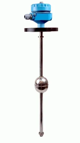
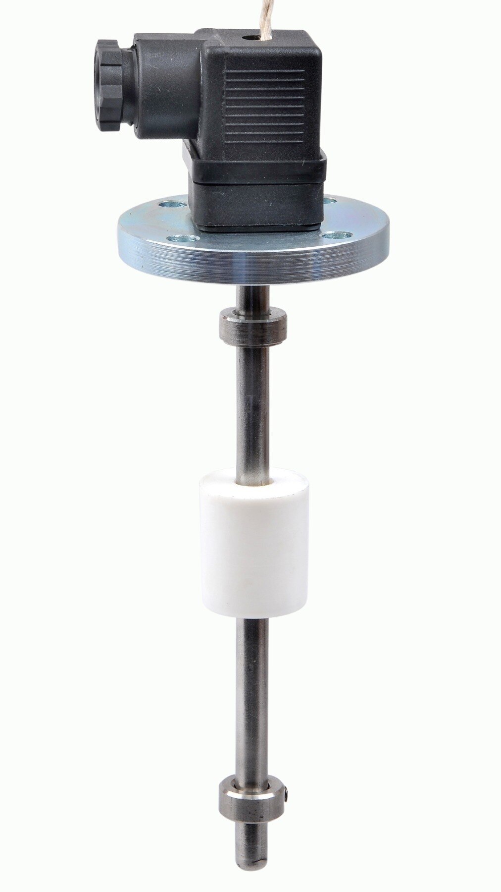
| Float | The liquid is reasonably clean and a guided float can move freely; mechanical level tracking is acceptable. | Solids, sludge, sticky deposits, turbulence or internal equipment can jam, foul or strike the float. |
| Hydrostatic | Liquid density is stable, the vessel pressure is known, and impulse lines or a flush diaphragm can be maintained. | Density changes with temperature, concentration or batching; gas pockets in liquid lines or plugged impulse lines will corrupt the reading. |
| Ultrasonic | The surface has a clear acoustic path, with little foam, vapour, condensation, dust or turbulence. | The beam crosses an inlet, ladder or agitator, or absorption and temperature gradients produce unreliable echoes. |
| Radar | You need non-contact measurement through vapour, pressure or temperature, and the antenna has a clear line of sight. | The antenna faces welds, coils, blades or filling streams, or the near-field distance reaches the operating level. |
| Capacitance | The liquid’s dielectric constant remains stable and the probe will not acquire a changing coating. | Conductivity, composition or deposits vary enough to change capacitance independently of level. |
Before selecting hydrostatic measurement, record density at minimum and maximum operating temperatures. Filpro Sensors Pvt Ltd can help you compare float, hydrostatic and ultrasonic choices by checking those process conditions against the instrument’s actual range and mounting limits.
Related products
 | Level Sensor Atex approved Float Level Transmitter : Over All Length: 300mm to 5000mm Input: 16V DC to 30V DC Output: 4-20mA / 0-10V DC Resolution: 5mm / 10mm... View product → |
 | Level Transmitter Float Level Transmitters Are Ideal For Continuous Level Monitoring In Water, Diesel, Chemical And Oils For Accurate Level Measurement. View product → |
Choose the mounting point and prepare the mechanical connection
Install the transmitter over a representative, calm section of the liquid surface, away from inlet streams, agitators, heating coils, ladders, wall welds and internal equipment. These level transmitter installation requirements prevent false echoes, turbulence errors and physical damage.
| Mounting arrangement | What it means | When it applies |
|---|---|---|
| Direct vessel nozzle | The sensor looks into the tank through a nozzle with a clear line of sight | Use when the beam or probe avoids obstructions and the nozzle does not place the surface inside the instrument’s blocking distance |
| Stilling well or bypass chamber | A controlled measurement path reduces turbulence and surface movement | Use when compatible with the radar frequency or ultrasonic design; confirm internal diameter, straightness, slots, vents and cleanliness |
| Remote seal or impulse connection | The transmitter measures through a diaphragm, capillary or routed pressure line | Use for hot, corrosive or inaccessible service; provide isolation, equalising, venting, draining and safe depressurisation |
Confirm the nozzle bore, flange rating and facing, thread type, gasket, pressure-temperature rating and insertion length. Check that the antenna, probe or diaphragm reaches the required reference point without entering the near-field or dead zone, and that the transmitter can be removed without vessel entry or draining.
- Keep ultrasonic transducers clear of vapour, condensation, foam, dusty surfaces and temperature gradients.
- Route differential-pressure impulse lines to prevent gas pockets in liquid lines and liquid pockets in gas-reference lines; protect them from freezing and plugging.
- Match wetted materials, seals and fill fluid to the chemical, temperature, cleaning and steam-in-place profile.
- Add an independent support for a heavy transmitter, long nozzle or remote seal so vibration cannot load the vessel connection.
Check wiring, hazardous-area compliance and the environment
Before connecting a level transmitter, verify its electrical limits, hazardous-area certification and installation environment. Use these level transmitter installation guidelines against the manufacturer’s wiring diagram and certificate, not against a generic instrument standard.
1. Confirm the supply voltage, output load limit and polarity. Select the specified cable type, gland, enclosure entry and ingress-protection rating; a mismatched gland can allow moisture into the terminals.
2. Follow the stated shield and grounding arrangement exactly. Grounding a shield at both ends can create circulating ground-loop current, while separating it from ground when the design requires grounding can increase signal noise.
3. Route the cable away from motor feeders, switching cables and variable-frequency-drive wiring. Check that the circuit has the specified barrier or galvanic isolator before energising an intrinsically safe loop.
4. Match the complete hazardous-area system to the actual gas, vapour or dust, zone or division, temperature class and ambient range. The transmitter certificate does not automatically approve an unlisted gland, cable entry, cover or wiring method.
5. Check that the location stays within the transmitter’s ambient temperature, vibration, flooding, impact and radiant-heat limits. Confirm that technicians can isolate, depressurise, drain and safely access the instrument without vessel entry for routine service.
For a differential-pressure transmitter, route impulse lines to prevent gas pockets in liquid lines and liquid pockets in reference-gas lines. Provide isolation, equalising, venting or draining points, plus freeze and plugging protection. Verify the enclosure is closed correctly before power is applied.
Plan commissioning, maintenance access and the final loop check
Plan service access before commissioning. Your level transmitter installation requirements should include a safe, repeatable route for inspection, calibration, cleaning and replacement without vessel entry. Confirm that operators can isolate, depressurize, drain and make the vessel safe; otherwise routine maintenance can require a shutdown.
Keep the instrument away from flooding, impact, excessive vibration and radiant heat. Apply the level transmitter installation guidelines to document these access and isolation points.
Check the transmitter configuration against the approved data sheet:
- Engineering units, lower range value and upper range value
- Damping, display orientation and alarm direction
- Failure mode, output trim and any empty-tank or false-echo mapping
- Tag number, power supply and signal destination
Complete the final loop check from the sensing element to the control system. Inject or create known low, mid-scale and high level conditions, then confirm that the transmitter, barrier or isolator, remote I/O and control-system display show the same values after scaling.
Test the configured high and low alarms, shutdown logic and fault response at the intended setpoints. A stable 4–20 mA continuity reading proves wiring continuity, not correct range configuration. Record each applied value, displayed value, alarm action and final setting before releasing the loop for service.
Frequently asked questions
What vessel information do you need before installing a level transmitter?
Record minimum and maximum operating levels, upper and lower reference points, nozzle location and length, nozzle bore, mounting space, empty-space distance, dead zones and internal obstructions such as coils, agitators, inlet pipes and stilling wells.
How do you choose the right level measurement principle?
Compare the liquid’s density, viscosity, conductivity, vapour, foam, temperature and pressure with the vessel geometry and operating conditions. Then select a principle such as radar, ultrasonic, hydrostatic or guided-wave radar that suits those conditions.
What should you check before mounting a level transmitter?
Verify the mounting point, nozzle dimensions, process connection, clearance, probe or antenna length, gasket, fasteners and access for removal, inspection and calibration.
What electrical and hazardous-area checks are required?
Confirm the supply voltage, signal type, cable routing, grounding, polarity, enclosure rating and hazardous-area certification match the installation zone and site documentation.
What must you verify during commissioning?
Check the configured empty and full references, engineering units, damping, alarm points and display. Test the complete signal loop from the transmitter through the control system and record the final readings.
Related products
 | Level Transmitter Hydrostatic liquid level transducers and transmitters with flush diaphragm is designed fora wide variety of level measurement applications. View product → |
 | Level Transmitter Ultrasonic Level Sensor is a non-contact ultrasonic continuous level measurement product based on sound technology. View product → |
 | Level Switch Filpro offers most reliable, cost effective Side Mounted Level Switch for point level sensing. View product → |
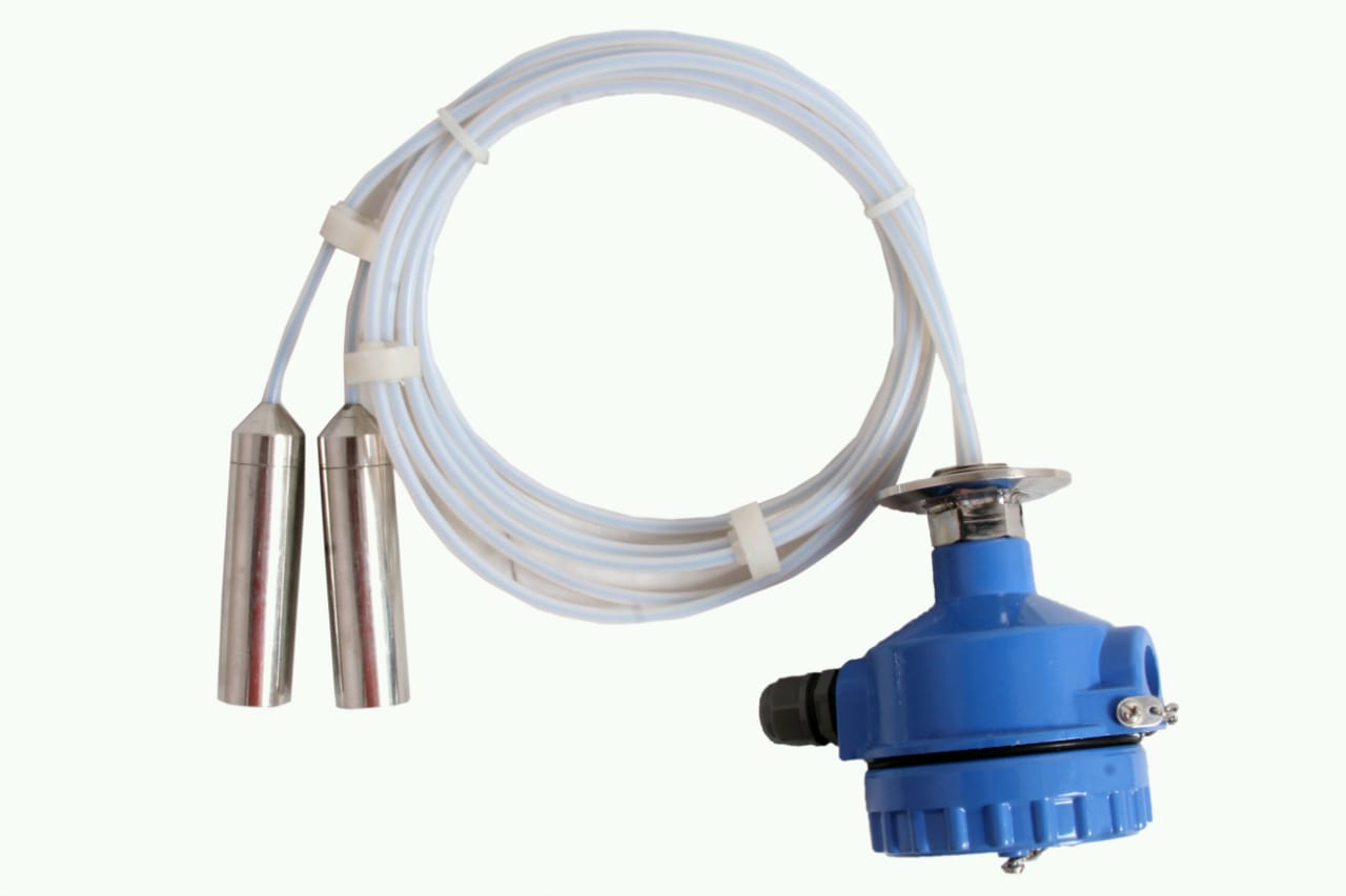 | Level Transmitter can be used for conductive as well as non conductive liquids. View product → |