The installation starts before you drill a hole or tighten a flange: the indicator technology, tank geometry, liquid properties and viewing position determine the correct arrangement. You will be able to plan the connections, mount the instrument, commission it safely and verify that its reading represents the tank’s usable level.
Key takeaways
- Match the indicator to tank geometry, access, process movement and viewing distance.
- Place connections at stable liquid zones, away from turbulence and obstructions.
- Align gauges without forcing flanges, panels or connecting pipes into position.
- Leak-test every connection before commissioning the level indication system.
Choose the indicator arrangement and measurement location
Choose the indicator arrangement by matching the tank geometry, available access, process movement and viewing distance to the measurement technology.
| Arrangement | Best fit | Check before selection |
|---|---|---|
| Top-mounted | Accessible roof; probe or float reaches the full range | Keep it clear of inlets, agitators, vortexes and internal structures |
| Side-mounted | Local reading required at operator eye level | Confirm minimum and maximum levels are reachable through side nozzles |
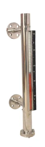
| External chamber | Turbulent, foaming, corrosive or difficult-to-inspect contents | Align upper and lower connections with the actual usable level range |
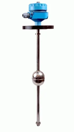
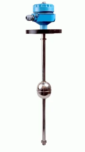
A top-mounted arrangement suits tank level indicator installation when the roof is safe to reach and the sensing element will not strike an inlet, agitator or dip tube. A side-mounted gauge gives operators a direct local reading, but the nozzles must cover the real minimum and maximum levels rather than convenient shell locations.
Select an external chamber when direct exposure would produce an unstable or unreliable reading. Its connections must correspond to the liquid range you need to measure; tank roof and floor elevations alone ignore nozzle height, bottom geometry and dead volume.
Keep sensing elements away from inlet jets, outlet suction, vortexes, foam collapse and agitator discharge. A stilling pipe or chamber can stabilise the signal, but adds response lag and a plugging path.
For hydrostatic liquid level indicator installation, establish liquid density and zero elevation before choosing the range: ΔP = ρgh. On a closed tank, connect both liquid-side and vapour-side pressures; a single liquid-side connection lets vapour pressure distort the reading. Provide accessible isolation, venting, draining or equalising points where the instrument requires them.
Prepare the tank, nozzles and isolation points
Before mounting, make the tank safe: shut it down, isolate every inlet, outlet, agitator and energy source, depressurise it, then drain or purge its contents. Confirm the atmosphere is safe before opening any connection. Follow the site permit, confined-space and hazardous-material procedures; an empty-looking tank can still contain vapour, pressure or residue.
Include the liquid level gauge installation procedure in management-of-change and mechanical-integrity controls when the site requires them.
- Measure the nozzle centreline, flange face or thread position, tank datum, minimum and maximum operating levels, roof clearance and distance to the viewing point.
- Check that the float, displacer, chamber, pointer, counterweight or probe has full travel without touching the shell, stiffeners or nearby pipework. Remove weld slag, scale, shipping restraints and debris.
- Install accessible isolation valves at tank connections. Provide vent, drain or equalising points where the instrument design requires them, and rate every valve for the tank pressure, temperature and liquid.
- Choose a gasket compatible with the liquid, pressure and temperature. Clean flange faces; inspect bolts and nuts for corrosion or damaged threads. Never use a gasket to correct misalignment.
- Support the instrument independently so the nozzle carries no pipe load.
| Connection | Check before mounting | Reject when |
|---|---|---|
| Flanged | Match rating, facing, bore and bolt pattern to the nozzle and instrument drawing. | The faces, holes or pressure ratings do not match. |
| Threaded | Confirm the instrument and process service permit a threaded connection. | Sealing, temperature, corrosion or maintenance conditions make threads unsuitable. |
| Chamber or sight gauge | Confirm vent, drain and isolation access, plus pressure-temperature and glass ratings. | The gauge cannot be safely isolated and depressurised during removal. |
Mount the gauge and indicator panel without creating alignment faults
1. Follow the liquid level gauge installation procedure by lifting the gauge into position without using flange bolts to correct misalignment. Fit the specified gasket between clean, parallel faces, then tighten fasteners in a diagonal sequence to the manufacturer’s torque using the site bolting procedure.
2. Mount an external chamber vertically, with its process connections level with the intended minimum and maximum liquid elevations. Confirm that the drain is at the low point and the vent is at the high point; otherwise trapped liquid or gas will distort the indication.
3. For a magnetic gauge, remove shipping restraints, insert the float in the marked orientation, and clean weld slag, scale and ferromagnetic debris from the chamber. Check that the indicator follower travels freely from bottom to top before connecting the chamber to service.
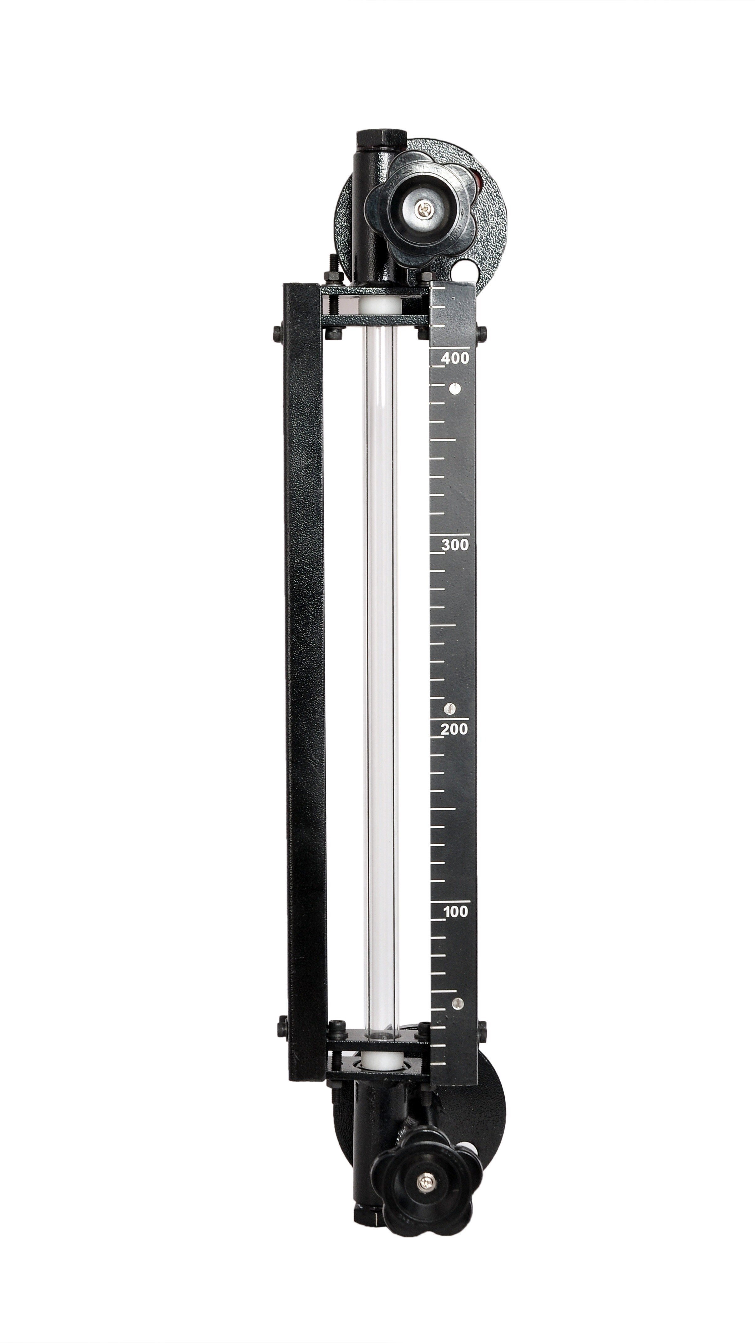
4. For a tubular glass gauge, inspect the glass, seals and guards, verify the pressure-temperature rating and gasket compatibility, and fit rated isolation valves, drain and vent arrangements before filling. Never treat the glass as a viewing window; it is pressure-retaining equipment.
5. For a float-and-board assembly, align the tank pulleys, route the rope without rubbing, immerse the float correctly, and leave the counterweight clear of obstructions. Set the board datum against a known tank elevation.
6. During liquid level indicator panel mounting, use the dimensional drawing for the cutout and retaining method. Fix the display at readable eye level, parallel to the tank or chamber, on a rigid independent support that carries no pipe load or vibration.
Preserve cable access, ventilation, enclosure sealing, and impact and weather protection, with enough clearance to prevent pointer fouling.
Connect hydrostatic and electronic indicators correctly
For a liquid level indicator installation using hydrostatic measurement, route liquid-service impulse lines without high points that trap gas, and include a vent point for trapped air. Route gas-service lines without low points that collect liquid, with a drain path for condensate.
Keep tubing short, continuously supported and shielded from heat, freezing, vibration and impact; long or uneven runs delay response and cause plugging or condensation errors.
| Service | Impulse-line arrangement | Main installation risk |
|---|---|---|
| Liquid service | Avoid gas pockets; provide a vent point | Trapped gas causes a false level |
| Gas service | Avoid liquid pockets; provide condensate drainage | Condensate changes the pressure signal |
| Closed tank differential pressure | Connect both high- and low-pressure legs | One connected leg responds to vapour pressure |
On a closed tank, the connection elevations establish the zero reference, while the upper leg compensates for vapour-space pressure. Fill, vent and equalise the sensing system as the instrument design specifies.
Set the range from actual operating density using ΔP = ρgh, not tank height alone; water used during commissioning can hide errors when process density differs.
For electronic display wiring and tank level indicator installation, check:
- Loop power, polarity, load, grounding, shielding and hazardous-area classification.
- Cable segregation, including separation of intrinsically safe circuits from other wiring.
- Shield termination against the plant grounding standard; do not assume both ends are correct.
- Panel cutout, terminal access and ingress-protection seal against the dimensional drawing during liquid level indicator panel mounting.
A powered display does not prove correct scaling, wiring or signal direction.
During tank level indicator installation, verify tightness and valve position, flush applicable lines, leak-test at permitted pressure, vent and fill the sensing system, then compare zero and span with the configuration and tank elevation measurements at more than one known level before admitting process liquid.
Inspect, leak-test and commission the completed installation
Final checks prove a safe and accurate tank level gauge installation when a written checklist passes, the permitted leak test holds, and the indication agrees with an independent reference.
- Confirm supports are rigid, fasteners are tight, gaskets are seated, valves are accessible, vents and drains are capped or routed safely, and guards are fitted.
- Check that pointers and floats move freely, with no cable or impulse line kinked. Flush or clean impulse lines and chambers when the process permits.
- Leak-test at the pressure allowed by the tank, gauge and site procedure. Inspect every flange, thread, valve, glass seal and chamber connection; stop immediately if any point leaks.
Fill the sensing system slowly with the commissioning fluid, vent trapped gas, and open isolation valves in the specified order. Equalize differential-pressure legs when required. A liquid level indicator installation commissioned with an unrepresentative fluid can hide density and zero errors.
| Indicator | Independent final check | Stop or adjust when |
|---|---|---|
| Float-and-board | Compare low, middle and high levels | Adjust the board or rope only after confirming pulley alignment |
| Magnetic | Check follower travel across the full range | Travel is restricted or does not match level |
| Electronic | Verify zero, span, output and alarms | Any value disagrees with the reference |
Record the serial number, range, density basis, datum, valve positions, leak-test result and commissioning fluid. Treat local indication separately from overfill protection: API 2350 applies to petroleum-tank overfill prevention, and a local gauge is not a high-high shutdown. Include the tank level indicator installation in management-of-change, training, inspection and mechanical-integrity controls when required.
Filpro Sensors Pvt Ltd can help resolve technology and connection mismatches before commissioning.
Related products
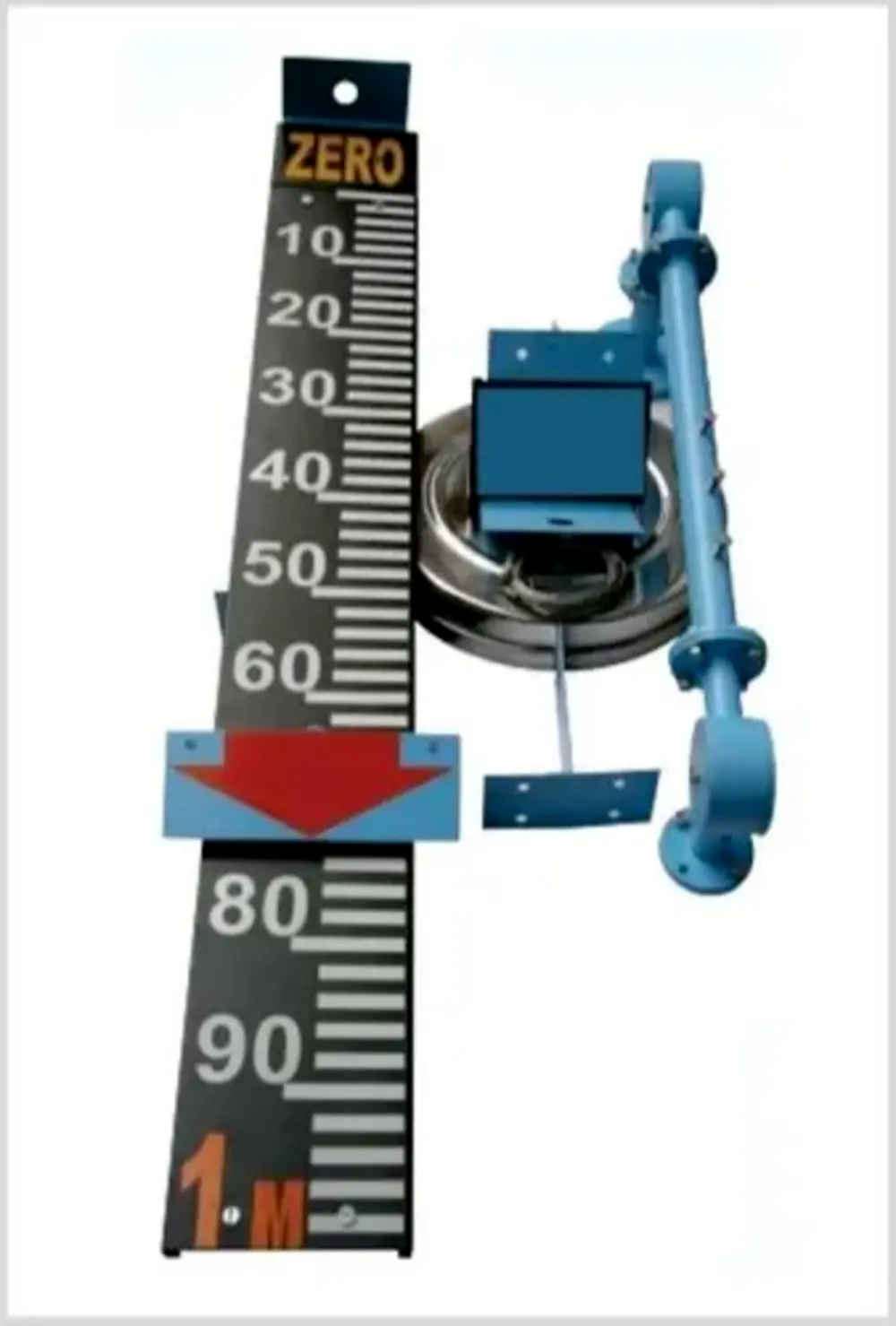 | Level Indicator The Float & Board Level Indicators consists of a float connected to a pointerthrough a rope via a set of pulleys. View product → |
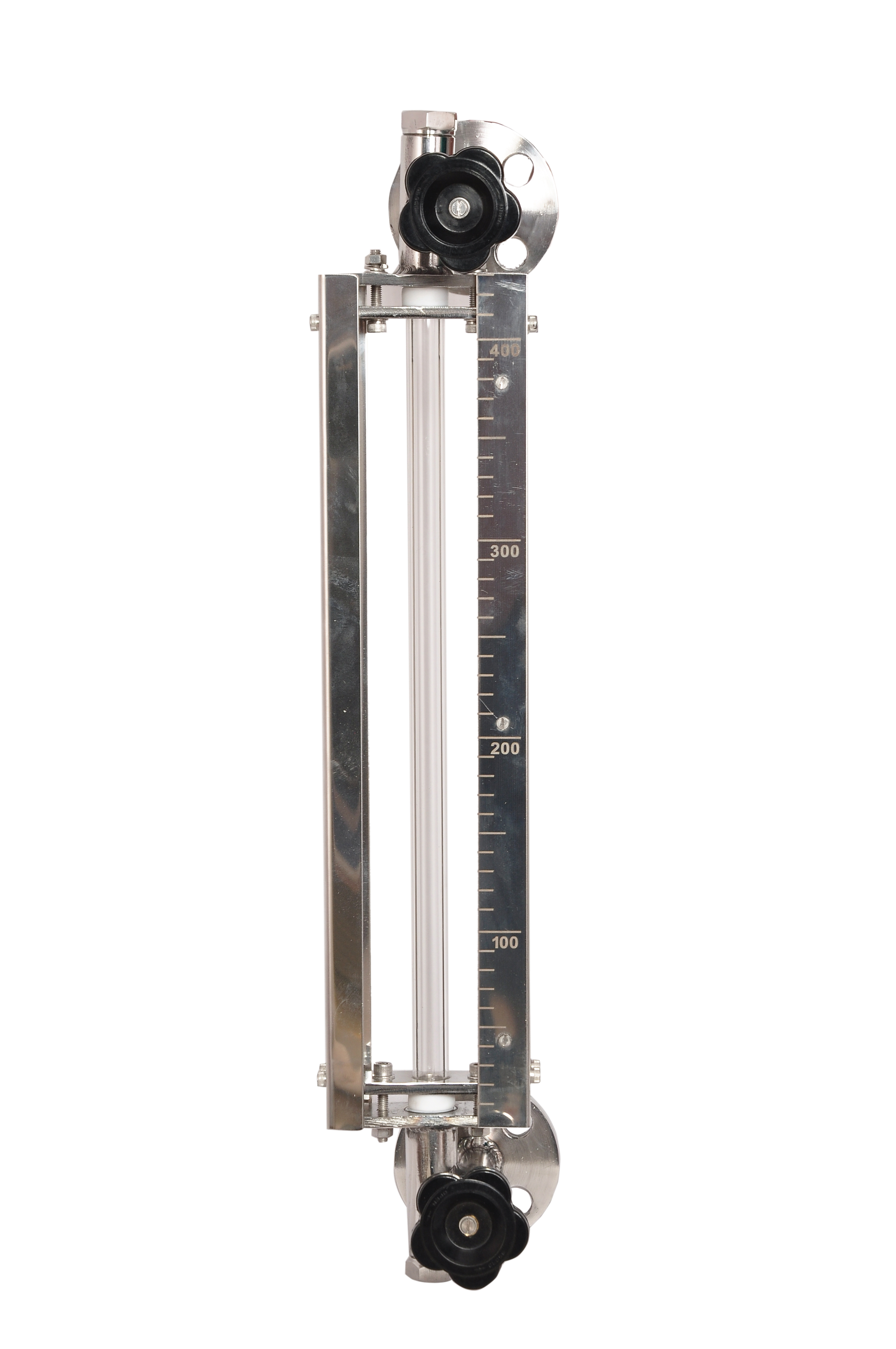 | Level Gauge Tubular Glass Level Indicator is used for visual level indication of liquid in storage and process tanks. View product → |
Frequently asked questions
How do you choose where to install a liquid level indicator on a tank?
Choose a stable measurement location that represents the tank level and remains visible from the operating position. Avoid turbulent inlets, outlets, agitators and areas blocked by supports or insulation.
What should you check before mounting a tank level gauge?
Confirm the nozzle size, flange or thread standard, centre-to-centre dimensions, tank pressure and temperature ratings, isolation valves, drain points and access for maintenance.
How do you prevent alignment faults during liquid level indicator panel mounting?
Set the gauge and panel against independently supported mounting points, then align the process connections without using bolts or tubing to pull components into position.
How do you commission a hydrostatic or electronic level indicator?
Check impulse lines, valves, wiring, polarity and grounding, then open isolation points in the correct sequence. Leak-test connections, compare the indication with the known liquid level and record the final reading.
Related products
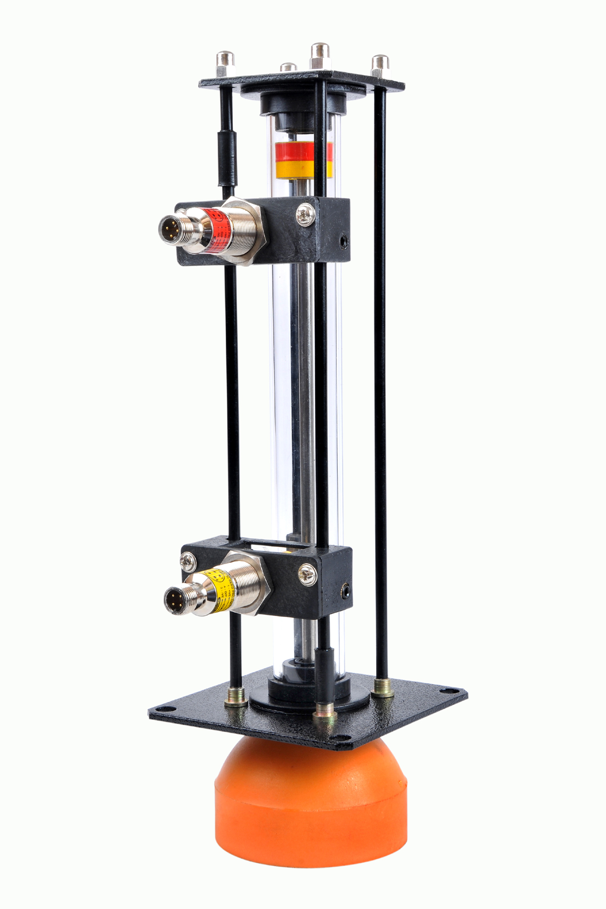 | Level Gauge Oil Level Indicator is designed to indicate the coolant and hydraulic oil level inside the tank with a visual indicator above the tank. View product → |
 | Level Switch Filpro offers most reliable, cost effective Side Mounted Level Switch for point level sensing. View product → |