A pump can remain electrically healthy while its suction loses the liquid needed for cooling, lubrication and stable hydraulic operation. By the end, you will be able to map the shutdown circuit, select a safe trip and reset level, prevent nuisance cycling, and verify that the protection works beyond the switch contact.
Key takeaways
- Stop the pump before the suction inlet draws air.
- Set the trip level above the minimum safe suction height.
- Use sensor materials compatible with the liquid and tank conditions.
- Test the cutoff using a simulated low-level fault.
What happens when the liquid falls below the safe suction level
When liquid falls below the configured trip point, a low level cutoff switch changes its electrical state and removes the pump’s start permissive. A relay, contactor, or control-system input then stops the motor before the suction inlet loses liquid.
This prevents dry running, which can remove seal lubrication and cooling, overheat seal faces or elastomers, damage impellers, and shorten bearing or motor life.
The cutoff is commonly a low-low shutdown set below a separate low-level alarm. The alarm gives you time to respond; the shutdown remains protective if nobody responds or communications fail. Use a latched trip with supervised manual reset when automatic restart could surprise personnel, cycle the pump, or restart it against an unresolved suction problem.
A complete proof test exercises the whole protective path:
- Expose the sensing element to the intended low level or simulate its specified signal.
- Verify the input card, trip logic, relay or contactor, and motor starter.
- Confirm that the pump actually stops or loses its permissive.
- Check the alarm, latch, reset, and fault indication.
Set the test interval through your risk assessment and maintenance program.
| Device | Protective role |
|---|---|
| Ordinary level indicator | Shows level locally; it does not stop the pump. |
| Continuous level transmitter | Supplies a measurement for inventory, trends, or proportional control. |
| High-level alarm | Warns of rising level; it does not protect against low suction. |
| Automatic pump controller | Starts or stops on a control strategy; it is not necessarily an independent low-level safeguard. |
| Low level cutoff switch | Trips at a defined low-low level to inhibit or stop the pump. |
A trip does not prove adequate suction: a blocked strainer, closed valve, hot liquid, or insufficient NPSHA can cause cavitation above the switch setpoint.
How the cutoff signal stops the pump safely
The low level cutoff switch sits in the pump’s permissive circuit, not in the motor’s high-current supply. While level is safe and all other permissives are healthy, a relay or contactor coil remains energised, allowing the motor starter to run the pump.
1. The switch detects the falling level and changes state at its trip point.
2. The relay drops out, or the safety input removes the run permissive. A broken cable, lost instrument power or unhealthy switch circuit must produce the same trip, not a false healthy signal.
3. The motor starter de-energises its contactor, disconnecting power from the pump motor. The overload relay remains a separate protection: it trips on excessive motor current, but it does not replace low-level protection.
4. The trip latches and records an alarm. When the level recovers, the pump stays stopped until an authorised person verifies the cause and presses a manual reset. A separate reset level, time delay or hysteresis prevents waves from repeatedly starting and stopping the pump.
5. Automatic restart is hazardous because level recovery can start the pump while the suction problem remains, or start it unexpectedly during maintenance. Use automatic restart only after a documented risk review.
Do not defeat the shutdown by leaving the starter in hand mode, bridging the switch, or using another start command. Apply the permissive to every start path, and control any authorised bypass with approval, a time limit, an alarm and documented restoration.
Proof-test the switch, wiring, input, logic, contactor drop-out, pump stop, latch and reset together.
How to set the trip level without inviting cavitation or short-cycling
Set the low-level cutoff switch from the pump’s required minimum submergence, not from the point where the suction opening is merely covered. Add the manufacturer’s submergence requirement above the suction elevation, then identify the resulting liquid elevation as the falling-level cut-off reference.
1. Establish the pump reference: record suction-centre elevation, required submergence, suction losses, liquid temperature and NPSHA. A surface vortex can entrain air before the tank reaches the nominal low-level point, so verify the margin during operation.
2. Convert that elevation through the tank geometry. Use the tank drawing to determine volume at cut-off and choose a higher restart elevation that provides useful hysteresis. Record both elevations against one datum, such as tank bottom or a marked nozzle centreline.
3. Check the installed switch rather than trusting its nameplate setpoint. Float buoyancy, mounting angle, cable movement, stilling-well dimensions and switch travel change the actual actuation elevation. Test and document falling-level cut-off and rising-level restart separately.
4. Observe the tank while pumping and filling. Waves, turbulence, an inlet jet and vortexing can move the float across its travel; filling flow can lift the level briefly and trigger premature restart.
Use a stilling arrangement, a time delay or a latched trip, but never delay shutdown long enough to lose prime or run dry.
Set the restart point above the cut-off by enough level and volume to prevent pump-induced fluctuations from crossing both contacts. That separation reduces short-cycling but removes some low-level storage from usable capacity. Automatic restart can also reintroduce an unresolved suction fault; a supervised manual reset is safer where the risk assessment requires it.
Which sensing method and wiring arrangement fit the liquid
Choose the sensing method by the liquid and the tank conditions, not by the switch name. A low level cutoff switch detects one point; it does not replace a continuous transmitter or prove that suction losses, a blocked strainer or high temperature have left adequate NPSHA.
| Method | Best fit | Conditions that can cause a wrong trip or missed trip |
|---|---|---|
| Mechanical float | Conductive or nonconductive liquids, including hydrocarbons and deionized water | Solids, scale, biological growth, viscous product or agitation can stick the float or damage its guide; confirm the material and temperature rating |
| Conductive probe | Water-based liquids with sufficient conductivity | It needs a reference electrode and fails as a choice for many hydrocarbons, deionized liquids or liquids that leave an insulating coating |
| Capacitance device | Conductive or nonconductive liquids, including hydrocarbons, when calibrated for the product | Product buildup changes the response; check coating tendency, solids, agitation and operating temperature |
| Ultrasonic instrument | Noncontact measurement where the surface gives a clean acoustic echo | Foam, vapor, turbulence, tank geometry and temperature-dependent sound speed can corrupt the level decision |
| Radar device | Hydrocarbons, conductive liquids, deionized liquids and difficult process surfaces | Foam, vapor, solids and agitation still require a suitable antenna, mounting and configuration; verify temperature limits |
Wire the switch to a relay or pump controller, and let that device command the motor contactor. Do not route motor current through a small level contact.
Filpro Sensors Pvt Ltd’s switches and controllers can be evaluated by contact rating, fail-safe state, reset logic and compatibility with the tank’s actual liquid rather than treating one device as universal.
Related products
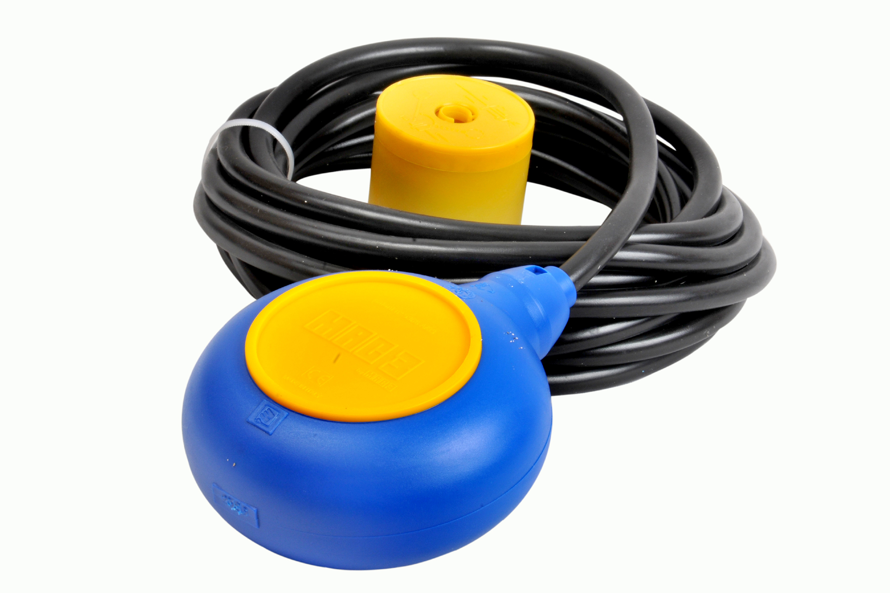 | Level Switch Cable Float Switch is mainly used for the automatic working of small pumps and cellar emptying pumps in liquids a little bit agitated. View product → |
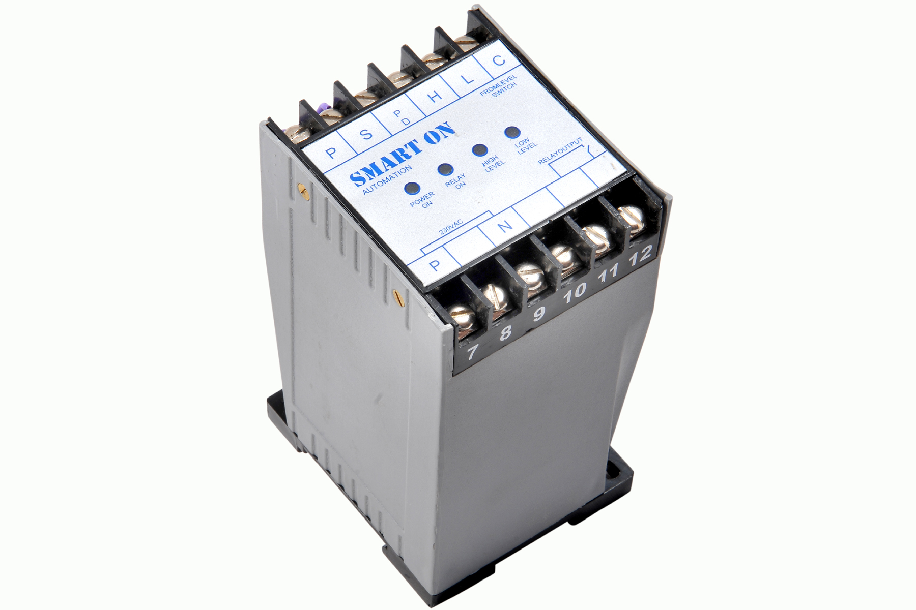 | Controller Filpro Sensors Pvt Ltd manufactures industrial Level Controller (Smart On) to automatically start & stop the pump. View product → |
How to prove the pump protection will work in a real fault
A low level cutoff switch sees liquid at one location; it cannot prove that the pump has adequate flow or suction conditions. Add low-flow, suction-pressure, discharge-pressure, motor-load or pump-condition signals to detect a blocked strainer, closed suction or discharge valve, loss of prime, impeller damage, abnormal pressure or operation outside the pump’s allowable range.
- Place the sensing element at its intended test level, or simulate its calibrated output. Confirm the switch changes state at the documented trip point and returns only at the separate reset level or after the specified hysteresis and delay.
- Verify that the input card receives the correct state, shows no wiring or channel fault, and drives the documented trip logic.
- Confirm the protective logic removes the pump permissive or de-energises the starter, and verify that the motor actually stops.
- Check the control-room alarm, local indication and fault indication. Confirm the event record identifies the correct pump and cause.
- Prove the trip latches after the level signal clears; attempt a reset without safe level and confirm it is refused.
- Restore the safe condition, reset the latch, and confirm the pump starts only through each permitted path: local, remote, automatic sequence, hand mode and maintenance or bypass controls.
- Test any bypass authorization, timer, annunciation and restoration indication; leave the bypass removed and record the result.
Repeat the proof test at the interval set by the site risk assessment and maintenance programme. A switch test alone is not proof of pump protection.
Frequently asked questions
What happens when liquid falls below the safe suction level?
The low level cutoff switch changes state and removes the pump’s start permissive before the suction inlet loses liquid. The control circuit then stops the motor or prevents it from starting.
How does a low level cutoff switch stop the pump safely?
The switch sends a signal to a relay, contactor, or control-system input. That device opens the pump’s run circuit or removes its start command.
How do you set the trip level without causing cavitation or short-cycling?
Set the trip point above the suction inlet’s minimum safe liquid height, allowing for vortexing, turbulence, measurement error, and pump rundown. Add restart hysteresis or a time delay to prevent repeated starts and stops.
How do you prove pump protection will work during a real fault?
Simulate a low-level condition, confirm the switch changes state, verify the relay or controller removes the run command, and check that the pump cannot restart until the reset conditions are met.
Related products
 | Level Switch Filpro offers most reliable, cost effective Side Mounted Level Switch for point level sensing. View product → |
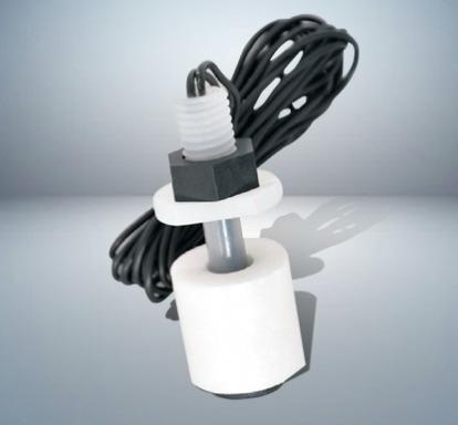 | Level Switch Plastic Miniature Level Switch is available in PP construction with PP Float Switching Voltage: 24V DC Switching current: 0.1A Mounting thread size:... View product → |
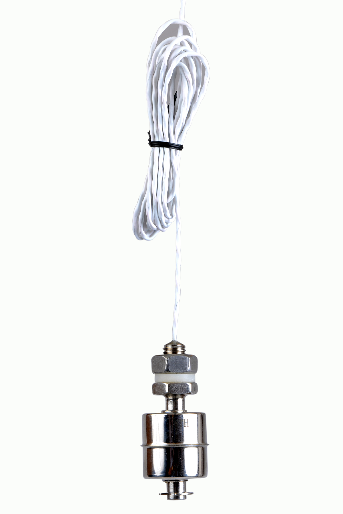 | Level Switch Stainless steel level switch - Miniature Stainless steel Miniature Level Switch is a compact construction, suitable for mounting vertically. View product → |
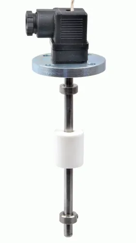
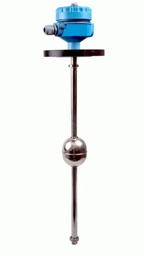
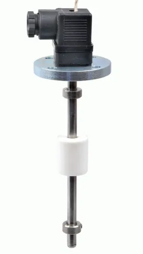
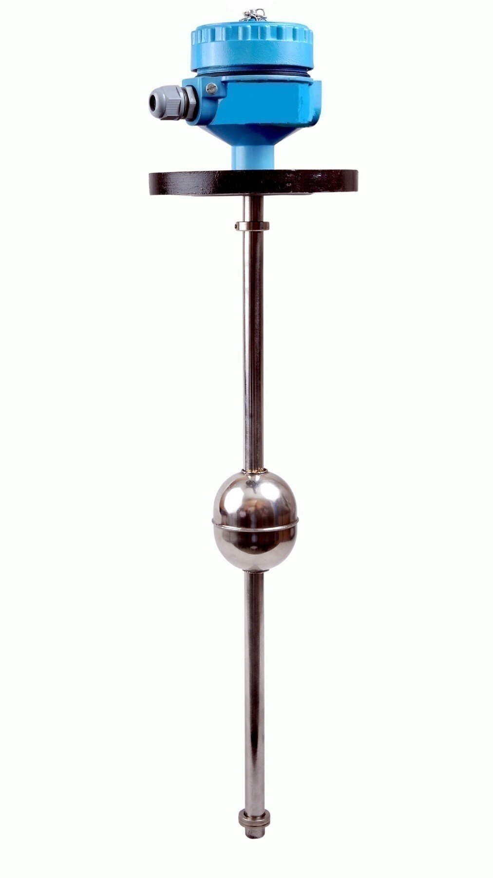
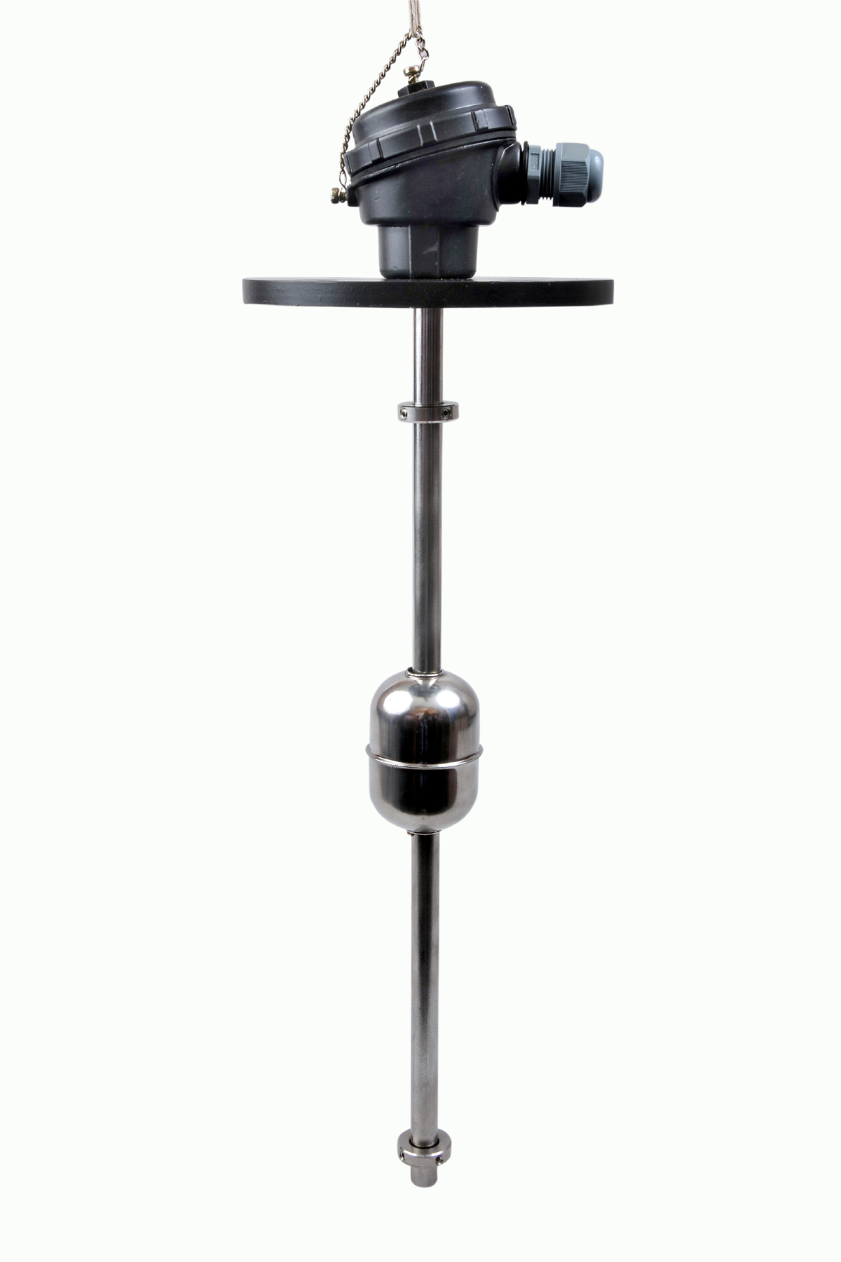 | Level Switch The Magnetic Level Switch consists of the non-abrasive float carrying permanent magnet and non-ferrous stem carrying one. View product → |