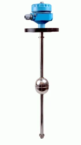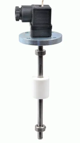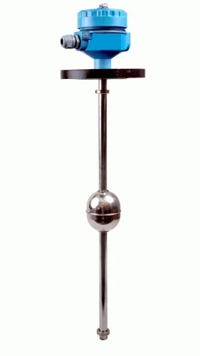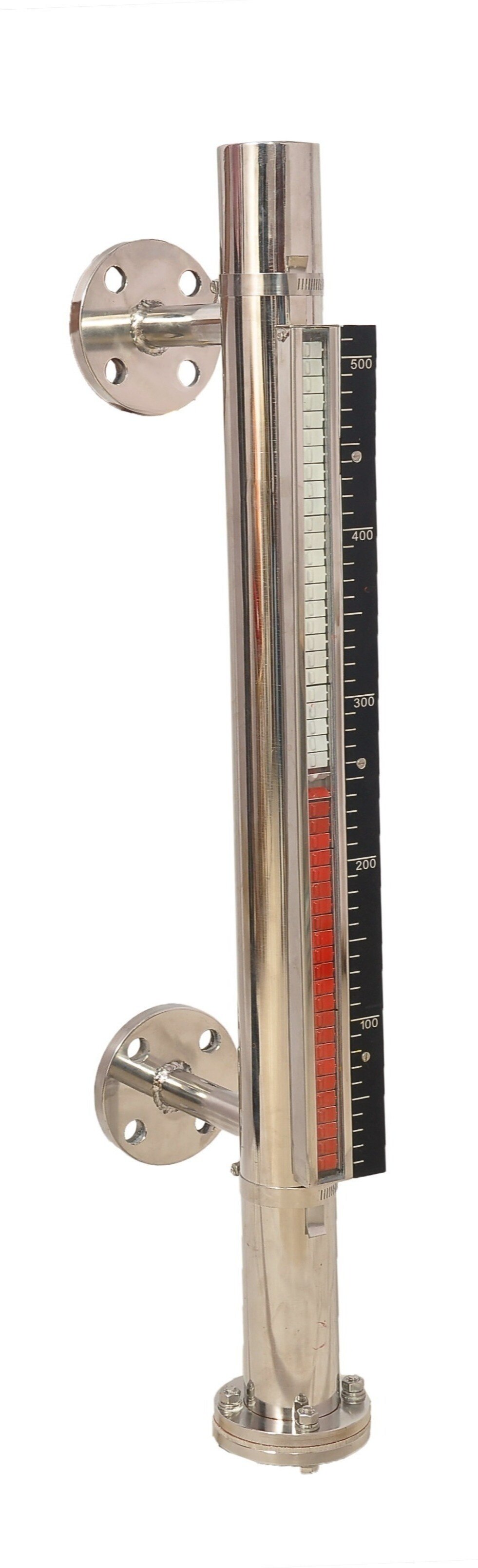
A magnetic level gauge turns the position of a buoyant float into an external visual reading while keeping the process liquid inside a sealed chamber. By the end, you will be able to trace the magnetic level gauge working principle, check whether the chamber and float suit your service, and identify installation conditions that can make the display misleading.
Key takeaways
- A buoyant magnetic float tracks liquid level inside a sealed chamber.
- The display shows level; a level switch only changes an electrical state.
- Incorrect chamber connections can make a stable reading inaccurate.
- Match float density, pressure rating, temperature, and materials to the process.
How the float and magnet create the level reading
The magnetic level gauge working principle starts with buoyancy: a sealed float containing a permanent magnet rises and falls inside a vertical, nonmagnetic chamber as the liquid surface rises or falls.
The magnet couples through the chamber wall to an external indicator, so the process liquid remains contained within the pressure boundary while operators read the float position outside it.
| Indicator format | How the reading appears | What moves |
|---|---|---|
| Bicolour magnetic flags | A boundary between two colours follows the float | Pivoting flags |
| Magnetic rollers | A contrasting colour band marks the float position | Rotating rollers |
| Follower magnet and scale | A marker travels beside a graduated scale | External follower |
The display does not measure colour, opacity, conductivity, dielectric constant, foam, or optical surface position. It shows where the float is; that position represents liquid level only when the float remains free and the chamber communicates correctly with the tank.
Keep the upper and lower process connections open, and check that isolation valves, nozzles, drains, vents, and gaskets are suitable for the service. A blocked connection or sticking float can leave the display showing a trapped or false level.
Read the visible boundary only after checking the scale against the installation datum and a known liquid level; the boundary is not an independently calibrated surface measurement.
How to read the display—and how it differs from a level switch
Read the boundary between the display colours against the scale. That boundary marks the external follower magnet aligned with the float magnet; do not read the top or bottom edge of a flag.
This is the practical magnetic level gauge working principle at the display: the indicator tracks float position and provides continuous local visual indication without electrical power. Common formats include a bicolour magnetic roller strip, a flapper display with contrasting faces, and an external scale with a magnetic follower.
| Device | What you see | What it can signal |
|---|---|---|
| Magnetic level gauge | Continuous position against a scale | Local indication only |
| Magnetic level switch | A contact changes at a configured point | High-level alarm, pump control or shutdown |
| Level transmitter | A measured signal across the operating range | Remote indication or control, if connected |
Use this procedure when specifying or checking the installation:
- Confirm the chamber scale zero matches the tank datum, then compare the displayed boundary with a known liquid level after installation or maintenance.
- Specify any switch or transmitter separately for setpoint, switching differential, electrical area classification, fail state and proof-testing method. It can signal a high level, but it cannot report the level between setpoints.
- Keep protection layers distinct: the passive gauge indication, level switch, alarm, shutdown logic and operator response each need defined failure and proof-test requirements.
A local gauge is not automatically an independent overfill-protection system. Treating its indication as the shutdown function leaves a failed display or missed operator response without a separate safeguard.
Why the chamber connections determine whether the reading is real
The magnetic level gauge working principle produces a trustworthy reading only when the bypass chamber is hydraulically connected to the tank. Install it with upper and lower nozzles, using top-and-bottom connections or suitably arranged side connections, so liquid reaches hydrostatic equilibrium with the vessel.
1. Keep both process connections open during measurement. A closed isolation valve, blocked nozzle, plugged impulse connection or unvented chamber can trap the float at a level different from the tank.
2. Check the connection size and condition. Small or restricted passages slow the indication while the tank fills or empties, particularly with viscous liquid or deposits in the nozzles.
3. Provide isolation valves for maintenance, a drain for controlled emptying and a vent for filling, removing air and safely depressurising the chamber.
4. Treat the chamber as part of the pressure-containing assembly when it connects to a pressurised vessel. The chamber, flanges, valves, drains, vents and gaskets need pressure-temperature ratings compatible with the service; the external flag rail is not the pressure boundary.
Isolation creates a maintenance hazard when operators assume the display remains live after closing a valve. Use managed or lockable isolation, then depressurise and verify the chamber before removing the float or opening any connection. A gauge isolated from the tank is a display of trapped liquid, not current tank level.
How to select the float and materials for the process
Select the float for the liquid, not chamber dimensions alone. Specify the minimum design specific gravity at the actual operating temperature and confirm buoyancy at that condition. A float that is too dense can sink, leaving a low or empty reading. Check dimensions against chamber bore and clearance; verify pressure, temperature, corrosion and magnetic-material limits.
| Application | Float selection | Required design check | Risk of the wrong choice |
|---|---|---|---|
| Single-liquid surface | Standard float matched to one liquid | Confirm buoyancy at minimum specific gravity and operating temperature | The float sinks or gives a false low level |
| Liquid interface | Interface float or displacer designed for both phases | Calculate buoyancy using both liquid specific gravities so it settles between them | A standard float follows one phase or fails to remain at the interface |
Evaluate viscosity, suspended solids, wax, crystallisation, coating and foam before approval. These conditions can make the float stick or restrict chamber connections. Colour, opacity, electrical conductivity and dielectric constant do not affect magnetic tracking.
Select the chamber, float, seals, process connections and indicator materials for the liquid’s chemical concentration and operating temperature. Do not choose them from the tank material alone: stainless steel can suit one concentration and temperature yet fail at another, while corrosive media can require a lining or different alloy.
Keep ferromagnetic objects away from the chamber and confirm float orientation, magnet condition and indicator-follower freedom. A nonmagnetic chamber wall preserves coupling; a damaged magnet, obstructed follower or nearby steel can make a visually intact display report the wrong level.
What to verify after installation and before relying on the gauge
Before relying on the reading, confirm that the chamber is plumb, fully filled and vented, and hydraulically connected to the tank with both upper and lower isolation valves open. This commissioning check tests the magnetic level gauge working principle in the installed system, not just the appearance of its display.
- Compare the local scale with a known liquid level after installation and after every maintenance intervention.
- Check the tank datum against the scale zero, and confirm that unequal top and bottom nozzle elevations have been included.
- Inspect float travel stops and verify that the float moves freely through the expected range.
- Check the temperature limit of the float, magnet, seals, magnetic flags or rollers, switches and transmitters. An intact display does not prove magnetic coupling remains within specification at high temperature.
- Test each attached switch at its actual setpoint, then verify alarm, shutdown and fail-state behaviour separately from the visual reading.
| Apparent error | What to investigate | Consequence |
|---|---|---|
| Scale differs from a known level | Tank datum, incorrect scale zero or unequal nozzle elevations | A consistent offset |
| Reading stops early | Float travel stop, obstruction or damaged float | A false fixed level |
| Reading differs from the tank | Closed valve, blocked nozzle, trapped gas or incomplete filling | A trapped chamber level |
Before removing the float or opening a connection, isolate, drain, vent, depressurise and verify zero energy under the site procedure. Filpro Sensors Pvt Ltd can help convert pressure, temperature, density, materials and connection details into a suitable gauge specification when site conditions make a generic choice unsafe.
Related product
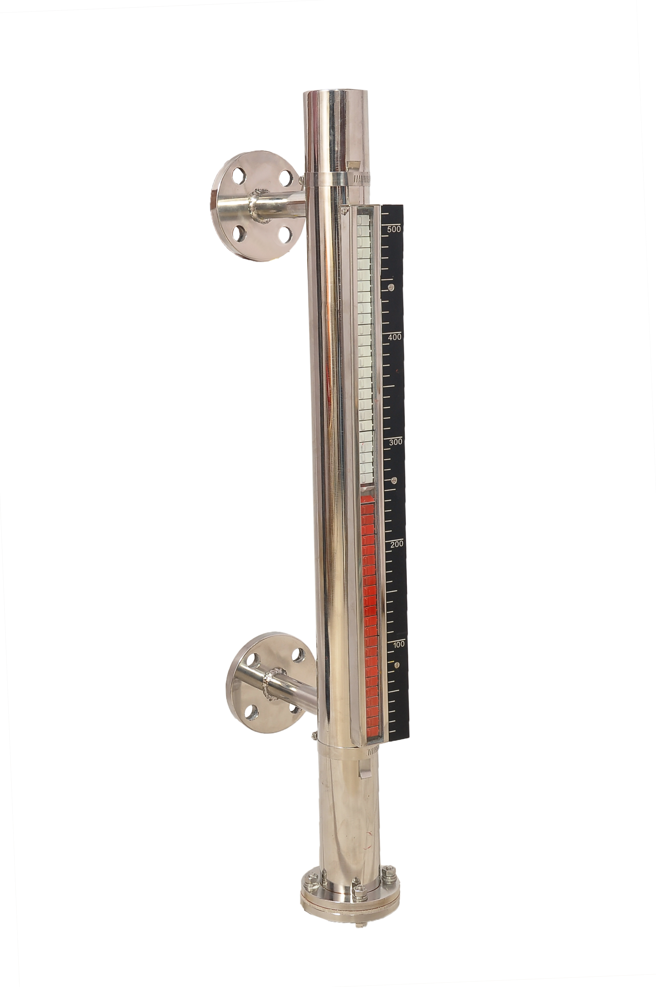 | Level Gauge FILPRO offers Magnetic Level Indicator provides clear, high clarity indication of liquid level. View product → |
Frequently asked questions
How does a magnetic level gauge create its reading?
A sealed float containing a permanent magnet rises and falls with the liquid. The magnet couples through the nonmagnetic chamber wall to an external indicator, which displays the level.
How does a magnetic level gauge differ from a level switch?
A magnetic level gauge provides continuous visual level indication. A level switch changes an electrical contact state at a set point for alarms, pumps, or interlocks.
Why do chamber connections affect the accuracy of a magnetic level gauge?
The upper and lower connections must communicate with the tank’s actual liquid and vapour spaces. Blocked, incorrectly positioned, or poorly isolated connections can leave the chamber level different from the tank level.
How do you select a float and materials for the process?
Check liquid density, pressure, temperature, viscosity, corrosion risk, and the required wetted materials. Select a float that remains buoyant and a chamber and seals compatible with the process.
What should you verify before relying on the gauge?
Confirm correct mounting, open isolation valves, clean connections, free float movement, visible indicator travel, scale alignment, and agreement with an independent level reference.