A level switch detects that liquid has reached a chosen point, then changes an electrical output so a pump, alarm, relay or shutdown circuit can respond. By the end, you will be able to trace that signal from the tank, choose between common sensing methods and specify the installation details that prevent false trips.
Key takeaways
- A level switch changes its output when liquid reaches a preset height.
- A float moves with the liquid and actuates reed contacts inside the stem.
- Mounting height sets the level at which the switch changes state.
- Separate start and stop heights prevent rapid pump cycling.
From rising liquid to a pump or alarm signal
How does a level switch work? It performs point-level detection: liquid movement reaches a defined operating zone, and the device changes an output state.
A high-level switch reports “liquid reached high,” while a low-level switch reports “liquid reached low.” A high-high switch adds a separate emergency threshold; none reports the liquid height continuously across the tank.
1. As liquid rises or falls, a float moves with the surface, or the liquid enters or leaves a probe’s sensing zone.
2. In a float switch, a permanent magnet inside the float enters a reed contact’s operating zone. The sealed contacts open or close without touching; normally open or normally closed wiring sets the signal sent to the control circuit.
3. That electrical change reaches a relay, PLC input, alarm, pump starter or shutdown circuit. The circuit can start filling, stop emptying, raise an alarm or trip equipment.
4. When the surface reverses, the switch resets at a separate point. This hysteresis prevents relay chatter and rapid pump cycling.
| Device | Output | What it tells you |
|---|---|---|
| Level switch | Discrete on/off state | A threshold such as low, high or high-high has been reached |
| Level transmitter | Continuous measurement signal | The changing liquid level between thresholds |
Conductive switches pass a low-voltage signal between electrodes through a sufficiently conductive liquid and grounded reference path, so they do not suit many oils or hydrocarbons. Ultrasonic point switches detect an acoustic change, but foam, vapour, turbulence or coating can cause missed or false detection.
Choose fail-safe wiring to match the hazard: power loss can trip a high-level shutdown, while a low-level permissive may use opposite logic.
How a float and reed contacts create the electrical signal
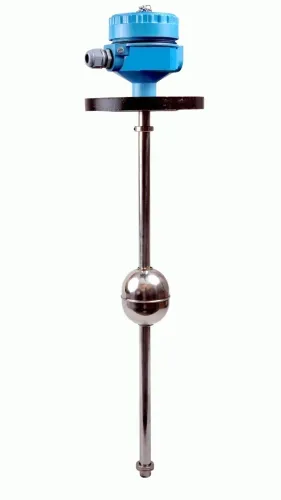
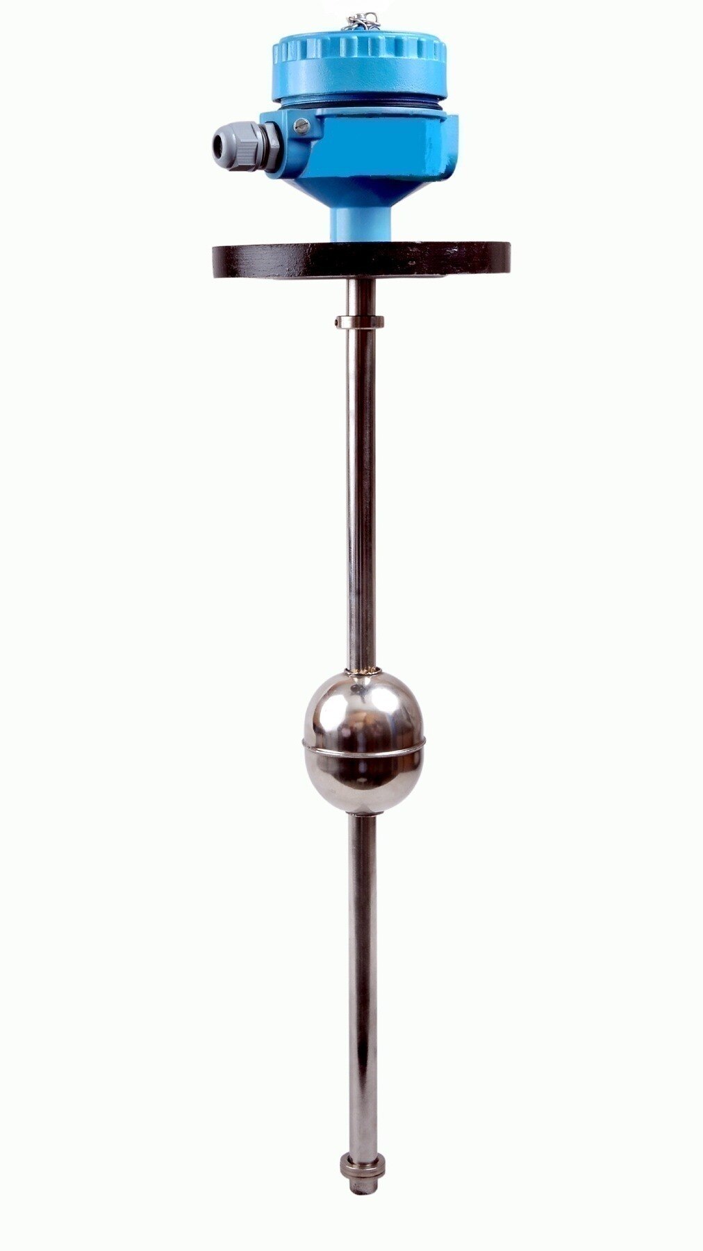
A float level switch turns liquid movement into an electrical output by moving a magnet past sealed contacts. As the liquid rises, buoyancy lifts the float; as it falls, the float drops. The attached permanent magnet enters the operating zone of the reed contacts, causing them to open or close without direct mechanical contact.
The electrical convention determines what the control circuit receives:
- A normally open level switch has open contacts in the specified normal or de-energized condition. When the magnet reaches the reed switch’s operating zone, the contacts close and complete the circuit.
- A normally closed level switch has closed contacts in that condition. Magnet movement opens the circuit instead.
- A reed switch level sensor connects through two or more wires to a control input, relay coil or alarm circuit. The receiving device detects continuity or loss of continuity and takes the programmed action.
Check the wiring diagram rather than guessing from “high-level” or “low-level.” Those labels identify the trip function, not whether the contacts are normally open or normally closed.
The actual actuation level depends on:
- Float shape and geometry
- Liquid density
- Vertical or horizontal mounting orientation
- Clear, unobstructed float travel
Buildup on the float can add weight or make it stick. A bent stem can shift the switching point, while a blocked float can leave the contacts permanently open or closed. Against a motor or solenoid load, route the contact through a correctly rated relay or contactor.
Where the switch sits determines the switching level
Mounting position sets the level at which a switch changes state because the float responds to its position inside the tank. A side-mounted level switch enters through a tank nozzle, but nozzle elevation alone does not guarantee the desired setpoint.
Specify the actual switching level, insertion depth, float clearance, travel direction, and liquid level at which the contact changes state.
| Option | Mounting arrangement | What determines operation |
|---|---|---|
| Side-mounted switch | Installed horizontally through a tank nozzle | Nozzle elevation, float geometry, insertion depth, clearance and travel direction determine the switching level |
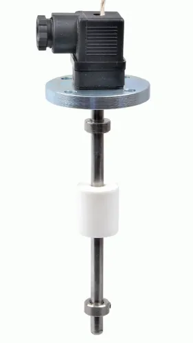
| Vertical level switch installation | Miniature switch installed from the tank top or bottom | Stem length, reference surface, float travel and the specified contact-change level determine the setpoint |
| Multiple reed switches | Several reed switches positioned along one stem | Each operating zone creates a separate level point at a defined elevation |
Several reed switches on one stem provide multiple level switch setpoints: low-level protection, pump-start, pump-stop, high-level notification and high-high alarm. Separating pump-start from pump-stop creates a control band, so surface movement does not repeatedly cycle the pump.
Keep the float path clear. Turbulence can move the float through its response zone, while an internal pipe, bent support or deposits can block travel or hold the float in place. Position the switch away from inlets, outlets and agitator flow, and keep obstructions outside the full float travel and response zone.
How pump control uses separate start and stop levels
Level switch pump control uses two separate pump start stop levels instead of one threshold. A low-level switch starts a transfer or filling pump, and the pump continues running until the liquid reaches the high-level switch. The high-level signal then stops the pump.
1. Set the low switch as the start point and the high switch as the stop point. This creates an operating band rather than making the pump respond to every small surface movement.
2. When the liquid falls to the low level, the switch changes state and energises the pump circuit. The pump fills the tank until the high-level switch changes state and removes that run command.
3. For an emptying pump, reverse the sequence: the high-level switch starts pumping out, and the low-level switch stops the pump when the liquid falls to the lower limit.
4. Confirm the actual contact logic before wiring. “Normally open” and “normally closed” describe the specified normal or de-energised state, not automatically a high- or low-level function.
The physical distance between switching and reset points is hysteresis. A hysteresis level switch keeps the relay from chattering when waves or vibration move the liquid around a threshold, which prevents rapid cycling.
Choose fail-safe level switch wiring for the hazard: a high-level shutdown may trip when power is lost, a cable breaks, or an internal fault is detected. A low-level permissive may use opposite logic.
Do not connect a motor or solenoid directly to contacts rated only for resistive loads. Use an interposing relay or contactor, plus the specified suppression device for inductive loads.
When a level switch is the right instrument—and when it is not
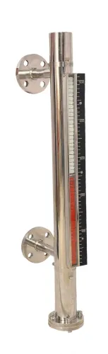
Choose a point level switch when you need a high, low or high-high alarm, pump interlock or dry-run protection. A level indicator vs level switch comparison is simple: an indicator shows level, while a switch changes state at one threshold.
| Technology | Best fit | Decisive limitation |
|---|---|---|
| Float | Clean liquids and simple point detection | Moving parts can stick; turbulence can cause switching |
| Vibrating fork level switch | Broad liquid compatibility and compact point sensing | Coating, heavy solids or extreme turbulence can affect vibration |
| Conductive | Water-based conductive liquids with a reference path | Conductive level switch limitations include unsuitability for many oils and hydrocarbons; it needs sufficient conductivity and a grounded tank or reference electrode |
| Capacitance | Non-contacting detection through a probe | The dielectric constant, probe geometry, grounding and buildup affect calibration |
| RF-admittance | Liquids that coat probes | It reduces coating errors but does not remove them |
| Ultrasonic point-level | Where no probe should enter the liquid | Foam, aeration, vapor, turbulence and obstructions scatter or absorb sound |
| Displacer | Applications needing buoyancy-based switching | Performance shifts when liquid density changes |
For a level switch vs level transmitter decision, choose a transmitter when inventory tracking or process control needs a continuous signal such as 4–20 mA. A discrete switch cannot show whether the tank is 20% or 80% full between its setpoints.
Specify these conditions before selecting the device:
- Process temperature, pressure, vacuum, corrosion and abrasion
- Wetted materials and process-connection pressure rating
- Enclosure protection, output type and load
- Actual high or low level, mounting orientation and response to turbulence
Filpro Sensors Pvt Ltd can help compare switching and control requirements, but these process conditions must determine the instrument choice.
Related products
 | Level Switch Filpro offers most reliable, cost effective Side Mounted Level Switch for point level sensing. View product → |
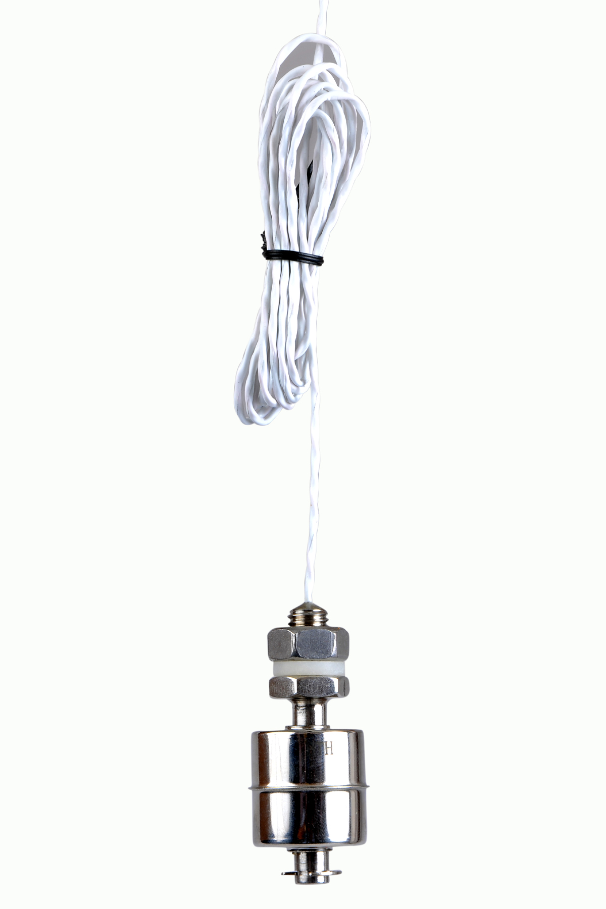 | Level Switch Stainless steel level switch - Miniature Stainless steel Miniature Level Switch is a compact construction, suitable for mounting vertically. View product → |
Frequently asked questions
How does a level switch send a pump or alarm signal?
When liquid reaches the switching zone, the device changes its electrical output state. A controller can use that change to start or stop a pump or trigger an alarm.
How do a float and reed contacts create the electrical signal?
A float follows the liquid level and contains a magnet. As it passes a reed contact inside the stem, the magnet opens or closes the contact circuit.
What determines the switching level in a tank?
The switch’s mounting position determines the level. The float and contact arrangement then changes state as liquid crosses that position.
Why use separate start and stop levels for pump control?
Separate levels create a switching gap, or hysteresis. The pump starts at one height and stops at another, preventing rapid on-off cycling.
When is a level switch the wrong instrument?
Use another instrument when you need continuous level measurement, a live level display, or multiple control points that one point-level switch cannot provide.
Related products
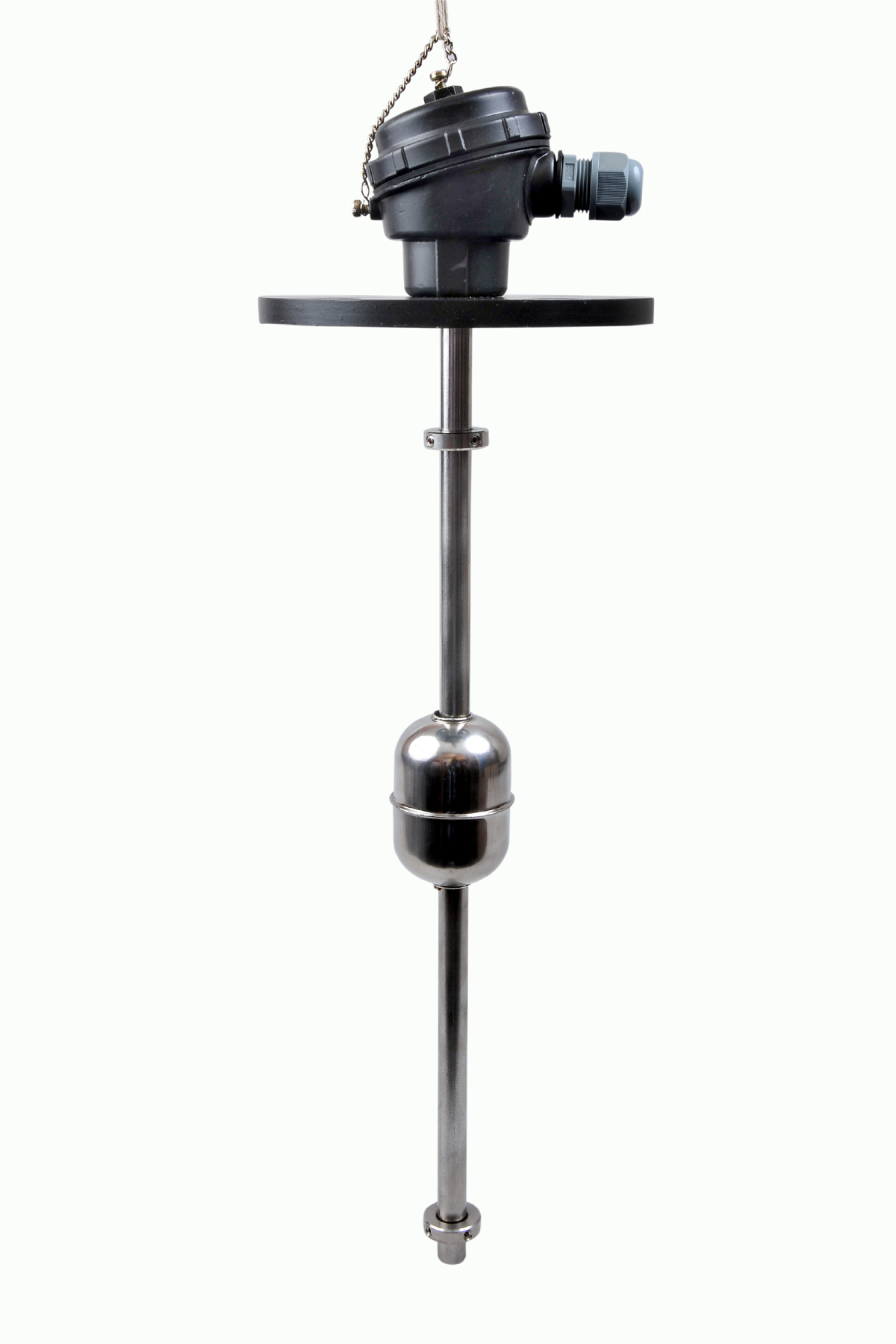 | Level Switch The Magnetic Level Switch consists of the non-abrasive float carrying permanent magnet and non-ferrous stem carrying one. View product → |
 | Level Transmitter Float Level Transmitters Are Ideal For Continuous Level Monitoring In Water, Diesel, Chemical And Oils For Accurate Level Measurement. View product → |
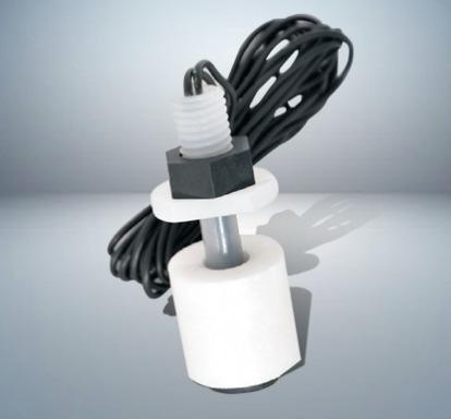 | Level Switch Plastic Miniature Level Switch is available in PP construction with PP Float Switching Voltage: 24V DC Switching current: 0.1A Mounting thread size:... View product → |