Viscosity changes how quickly a float moves, how easily a diaphragm or probe becomes coated, and how reliably a sensor detects a stable surface. By matching the instrument to density, temperature, coating tendency, tank geometry and process movement, you can choose a measurement method, install it correctly and verify its readings under real operating conditions.
Key takeaways
- Match transmitter technology to viscosity, density, temperature and tank geometry.
- Use flush connections and suitable impulse-line layouts to prevent plugging.
- Account for coating, foam, trapped air and changing liquid density.
- Test zero, span, response time and alarm points before trusting readings.
Why viscous liquids produce misleading level readings
Viscous liquids produce misleading readings because they do not form or move like water-like products. Slow movement delays response, adhesion leaves residue on sensing surfaces, and trapped air can interrupt pressure transmission. The result is a reading that reflects the instrument’s recent conditions rather than the liquid’s actual level.
Common sources of error include:
- Temperature-dependent viscosity: heating can make the product flow, while cooling can increase coating and leave a float or displacer moving sluggishly.
- Sensor coating: material on a probe, diaphragm, or antenna can appear as product, weaken the signal, or create a false echo.
- Density change: a hydrostatic transmitter measures ΔP = ρgΔh, not level directly. If density rises 10% while calibration stays unchanged, the indicated level can be approximately 10% wrong.
- Surface uncertainty: foam, vapor, and a poorly defined surface can reduce the reliability of non-contact radar.
- Contact measurement: guided-wave radar, capacitance probes, floats, and displacers remain exposed to coating, bridging, drag, or fouling.
A level transmitter for viscous liquids therefore needs evaluation against the actual process, not a water demonstration. Non-contact radar usually treats viscosity as a secondary factor, but dielectric constant, tank geometry, vapor, foam, and antenna buildup control its signal margin.
Capacitance readings shift when coating or product composition changes, while displacer accuracy depends on stable density and free mechanical movement.
Validate viscous liquid level measurement against an independent reference at several levels, temperatures, and representative product compositions. That test exposes errors a clean, room-temperature water trial will miss.
How to choose the measurement technology from process data
A level transmitter for viscous liquids should be chosen from tank conditions, not viscosity alone. Start with minimum and maximum level, operating temperature and pressure, density variation, dielectric constant or conductivity, solids, foam, vapor, agitation, buildup and cleaning access.
| Technology | What it means | When it fits |
|---|---|---|
| Free-space radar level transmitter | Non-contact microwave measurement | Preferred when coating is likely; check dielectric constant, foam, vapor, nozzle position, agitators and antenna fouling |
| Guided-wave radar | A probe measures the return inside the tank | Suitable when the probe will not bridge, coat or carry mechanical load; confirm cleaning method and coating thickness |
| Ultrasonic level measurement | Non-contact acoustic measurement | Use with a clear acoustic path and stable surface; vapor, condensation, foam, fumes and agitation can weaken or distort the echo |
| Hydrostatic or differential pressure | Infers height from ΔP = ρgΔh | Use when density is stable; a 10% density change creates about a 10% level error if the original density remains configured |
| Float level transmitter | A buoyant float follows the liquid surface | Consider only when the float will move freely and coating will not make it stick |
Free-space radar is often the safest starting point for a coating-prone viscous product because its sensing element stays outside the liquid, but deposits on the antenna can still create false echoes.
Ask the process owner for the full viscosity range, temperature at startup and operation, tank and nozzle dimensions, pressure, density limits, surface behavior, expected buildup and cleaning procedure before specifying range, antenna or diagnostics.
How to install hydrostatic measurement without plugging or density error
A hydrostatic level transmitter for viscous liquids must sense pressure through a connection that will not fill with stagnant product. Mount the process connection at the tank bottom or below the lowest measured level, using a flush diaphragm rather than a small-bore impulse line.
1. Fit the hydrostatic level transmitter with a flush diaphragm and a short, direct process connection. Avoid narrow impulse tubing, elbows and dead legs where viscous material can cool, harden or accumulate. Keep the diaphragm face flush with the vessel wall so sediment does not form a shelf over the sensing point.
2. Install the connection where you can isolate, drain and clean it without entering the vessel. Add insulation or heat tracing when the product temperature must remain above its pour point.
If you use remote seals, specify the fill fluid and capillary length for the full temperature range; temperature effects can shift the reading and add response lag.
3. Calibrate using the actual product density at the operating temperature. The transmitter measures pressure, not height: level equals pressure divided by density and gravitational acceleration. Enter density compensation through a live density input, a composition-based correction, or separate calibration values when density changes between batches.
4. Check zero with the vessel at the defined reference condition, then verify span at several known levels. Compare the reading with an independent reference at minimum and maximum temperatures, product compositions and levels; water-only testing will not expose density error.
A 10% density change produces about a 10% level error when the transmitter retains the old density value. Record the density source, temperature and correction method in the calibration record.
How to prevent coating, foam and tank geometry from causing false readings
Choose the installation that keeps the sensing surface clean, the signal path open and the liquid representative of the tank. Radar for viscous liquids usually tolerates viscosity better than contact probes, but foam, buildup and poorly placed nozzles can still create false echoes.
1. Mount a radar or ultrasonic sensor away from the inlet, agitator, heating coil and internal supports. Aim the beam at the quietest surface area, then use false-echo suppression only after the tank is empty or at a known low level.
2. Keep ultrasonic sensors out of vapour plumes and condensation zones. Configure temperature compensation, measurement range and blanking distance; foam or an irregular surface can still weaken the return beyond recovery.
3. Use a stilling well for radar or float measurement when agitation causes instability, but size its bore and equalization openings for the product. A narrow or poorly drained chamber lets viscous material stagnate, harden and trap the float.
4. Treat guided-wave radar as a contact measurement. Select a probe that suits the viscosity, coating tendency and cleaning method, provide mechanical support against loading, and leave access for removal; coating can create a false interface.
5. Specify a capacitance level transmitter only when dielectric constant and coating behaviour remain stable. Keep the probe clear of tank walls and braces, and use buildup compensation when the instrument provides it.
Verify the installation against an independent level reference at low and high levels, temperatures and representative product compositions. Include foam, agitation and the actual cleaning condition in the acceptance test; water alone will not expose every false reading.
How to test the installation before relying on its output
Prove a level transmitter for viscous liquids against an independent level reference, not against water alone. Record the transmitter output at low, middle and high levels while the product covers its actual temperature range and representative composition. A water test can miss density error, probe coating, foam and vapor effects.
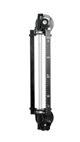
- During level transmitter commissioning, verify zero and span, then compare readings with a calibrated sight glass, dip measurement or another independently calibrated method.
- Repeat the comparison at the lowest and highest operating temperatures, after the tank reaches thermal stability. Record temperature, density or blend ratio, tank level and transmitter output.
- Test the actual product at each composition that changes density, dielectric constant or solids content. For a DP transmitter, check ΔP = ρgΔh; a 10% density change creates about a 10% level error if the configured density stays fixed.
- Inspect the probe, diaphragm or antenna after the test. Coating, a slow response, false echoes or a drifting capacitance reading requires cleaning, revised diagnostics or a different technology.
For a transmitter supplied by Filpro Sensors Pvt Ltd, put the tested density range, temperature range, reference method and maximum permitted error in the commissioning record. Accept the installation only when errors remain within your process limit at every tested level and state; do not average away a failure at one condition.
Related products
 | Level Transmitter Hydrostatic liquid level transducers and transmitters with flush diaphragm is designed fora wide variety of level measurement applications. View product → |
 | Level Transmitter Ultrasonic Level Sensor is a non-contact ultrasonic continuous level measurement product based on sound technology. View product → |
Frequently asked questions
Why do viscous liquids cause misleading level readings?
Slow movement delays response, while adhesion, coating and trapped air can disrupt pressure transmission or sensing-surface readings.
How do you choose a level transmitter for viscous liquids?
Compare viscosity, density, temperature, solids content, foam, tank geometry and required response time before selecting the technology.
How can hydrostatic measurement avoid plugging and density error?
Use suitable flush connections, minimise or heat-trace impulse lines where required, and compensate for density changes in calibration.
How do you test a transmitter before relying on its output?
Check zero and span, compare readings at known levels, verify response time, and test configured alarms across the operating range.
Related products
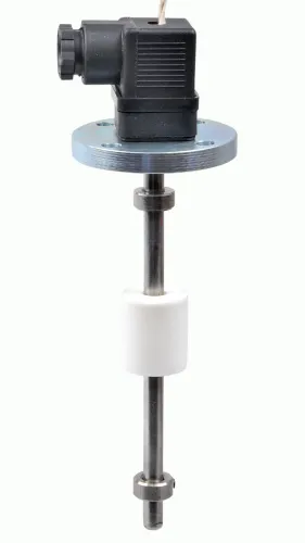
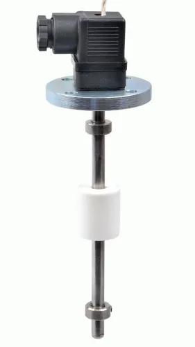
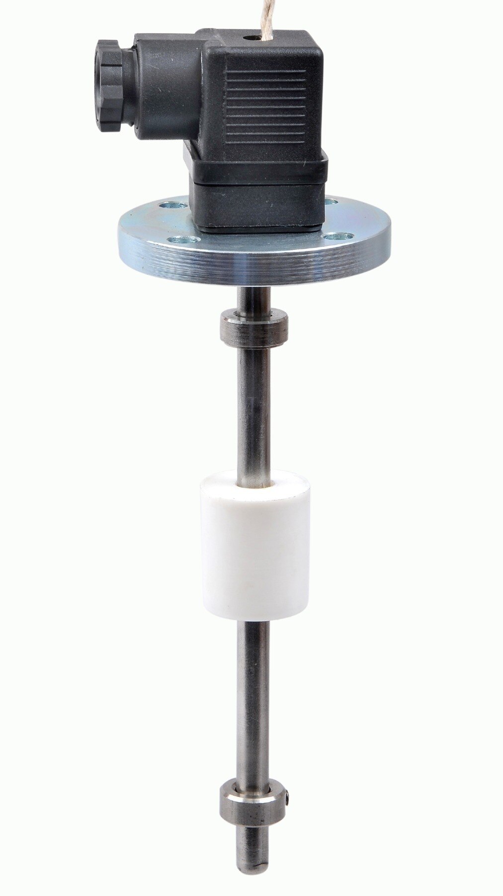
 | Level Transmitter Float Level Transmitters Are Ideal For Continuous Level Monitoring In Water, Diesel, Chemical And Oils For Accurate Level Measurement. View product → |
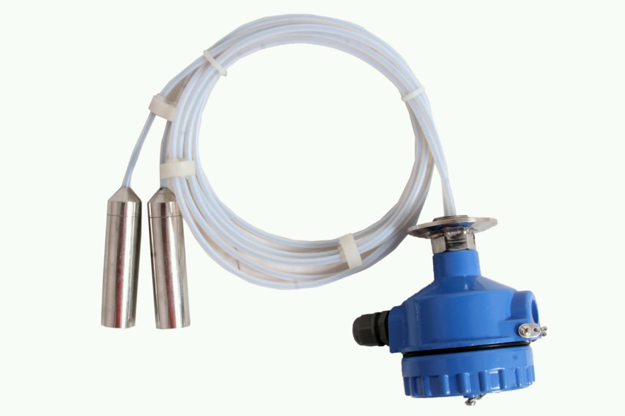 | Level Transmitter can be used for conductive as well as non conductive liquids. View product → |
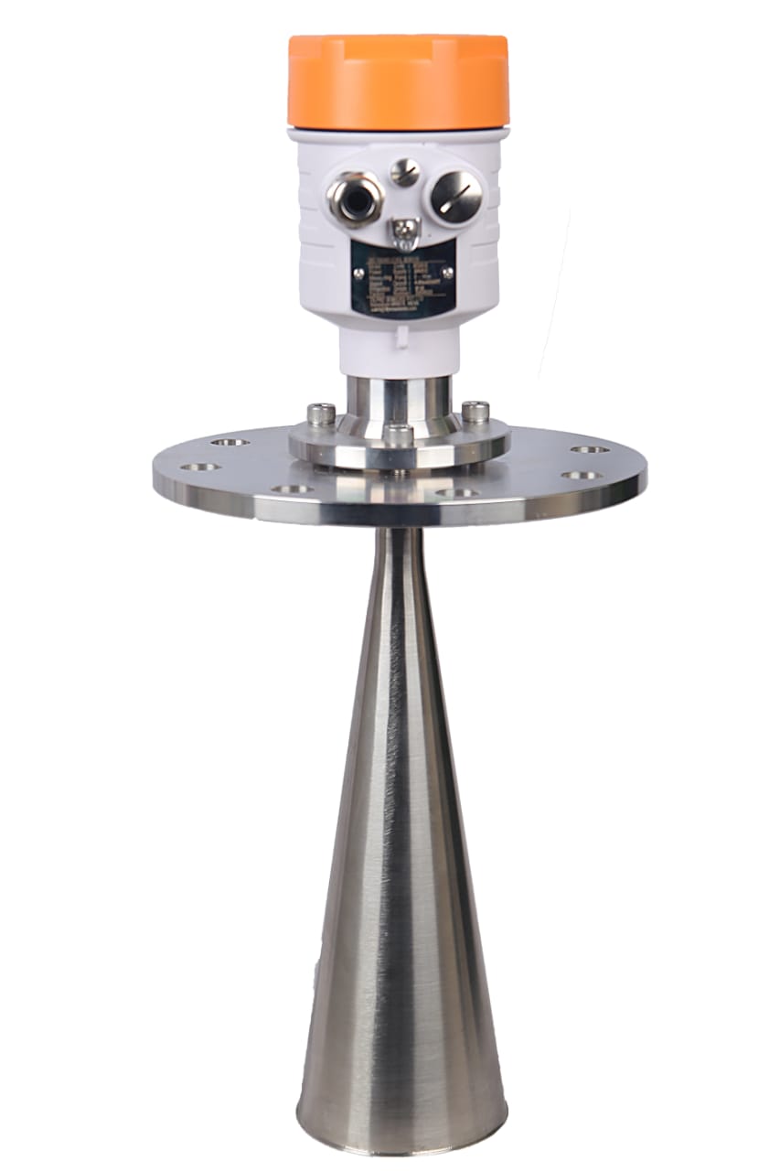 | Level Transmitter FILPRO offers professional Radar Level Transmitter. Our radar level transmitter uses radar to continuously measure non-contact liquid level, the... View product → |