A pump does not decide when to run by itself: a level sensor detects a changing liquid condition, a controller applies start and stop logic, and a relay or contactor switches motor power. By the end, you will be able to trace that sequence, specify the wiring and protection, and set up a system that avoids overflow, dry running, and rapid cycling.
Key takeaways
- Use a float switch for simple on-off sump control.
- Route the sensor through control logic and a motor starter.
- Set separate start and stop levels to prevent rapid cycling.
- Test alarms, overload protection and pump rotation before commissioning.
From changing liquid level to a pump command
A level controller for pump automation converts a detected liquid-level change into a start or stop command. A float switch changes state when the liquid reaches its set height; a continuous transmitter instead sends a signal, commonly 4–20 mA, representing the configured measurement range. The controller interprets that input and applies its programmed logic.
- At the rising start level, the controller energises an output relay.
- That relay operates a contactor, motor starter, or VFD command circuit.
- The contactor or starter switches motor power to run the pump; the controller relay must not be assumed suitable for switching motor current directly.
- At the falling stop level, the controller de-energises the output, and the contactor removes power from the pump.
A level controller with pump control normally uses separate start and stop thresholds. Their gap, called hysteresis or deadband, prevents rapid cycling when the level fluctuates near one point.
Test both thresholds with the real inflow, discharge restriction, contactor or VFD delay, and pump capacity: liquid can keep rising after a start command if inflow exceeds pumping rate.
Set a defined response for an open 4–20 mA circuit, lost transmitter power, or out-of-range signal; do not treat every fault as a valid low level. A low-level stop also does not prove dry-run protection, because blocked suction or loss of prime can leave the pump without liquid.
Retain motor overload and high-temperature protection, and use a manual-off-automatic selector without allowing manual mode to bypass critical interlocks.
The control-panel path: sensor, logic, starter and motor
A level controller pump control system keeps the sensing circuit separate from the motor-power circuit. The controller interprets the level input and operates a relay output; that output energises a contactor, motor starter or VFD enable input.
Never connect a pump motor directly to a controller relay unless its nameplate explicitly gives a suitable motor-load rating.
Wire the control-panel path in this order:
- Connect the level transmitter or switch to the controller input, using the specified supply voltage and signal type. For a 4–20 mA transmitter, configure the lower and upper range and define the response to an open circuit, lost transmitter power and out-of-range current.
- Feed the controller from a protected control-circuit supply. Use a fuse or miniature circuit breaker rated for the controller, sensor and contactor-coil load.
- Route the controller output through the manual-off-automatic selector and into the contactor coil or VFD run command. Keep emergency-stop and critical trip contacts in the control circuit, not only in software.
- Feed the motor through a correctly rated isolator, short-circuit protection, contactor or starter, and overload relay. Connect the motor frame and panel enclosure to protective earth.
- Set the overload to the motor manufacturer’s nameplate full-load current and select the contactor for the motor’s voltage, starting duty and AC-3 rating. Size motor conductors for that current, installation method, voltage drop and prospective fault current.
Add minimum-run or anti-short-cycle timing, plus low-level, overload, temperature and seal-leak trips where the pump requires them. A level controller for pump control cannot detect a blocked suction or lost prime by itself.
Choose the sensing method for the liquid and the duty
Choose the sensing method from the liquid’s behaviour and the pump duty, not from measurement range alone. A level controller for automatic pumping must receive a reliable level signal at the point where the pump decision is made.
| Technology | Best fit | Check before selecting |
|---|---|---|
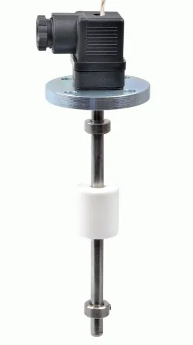
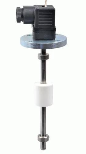
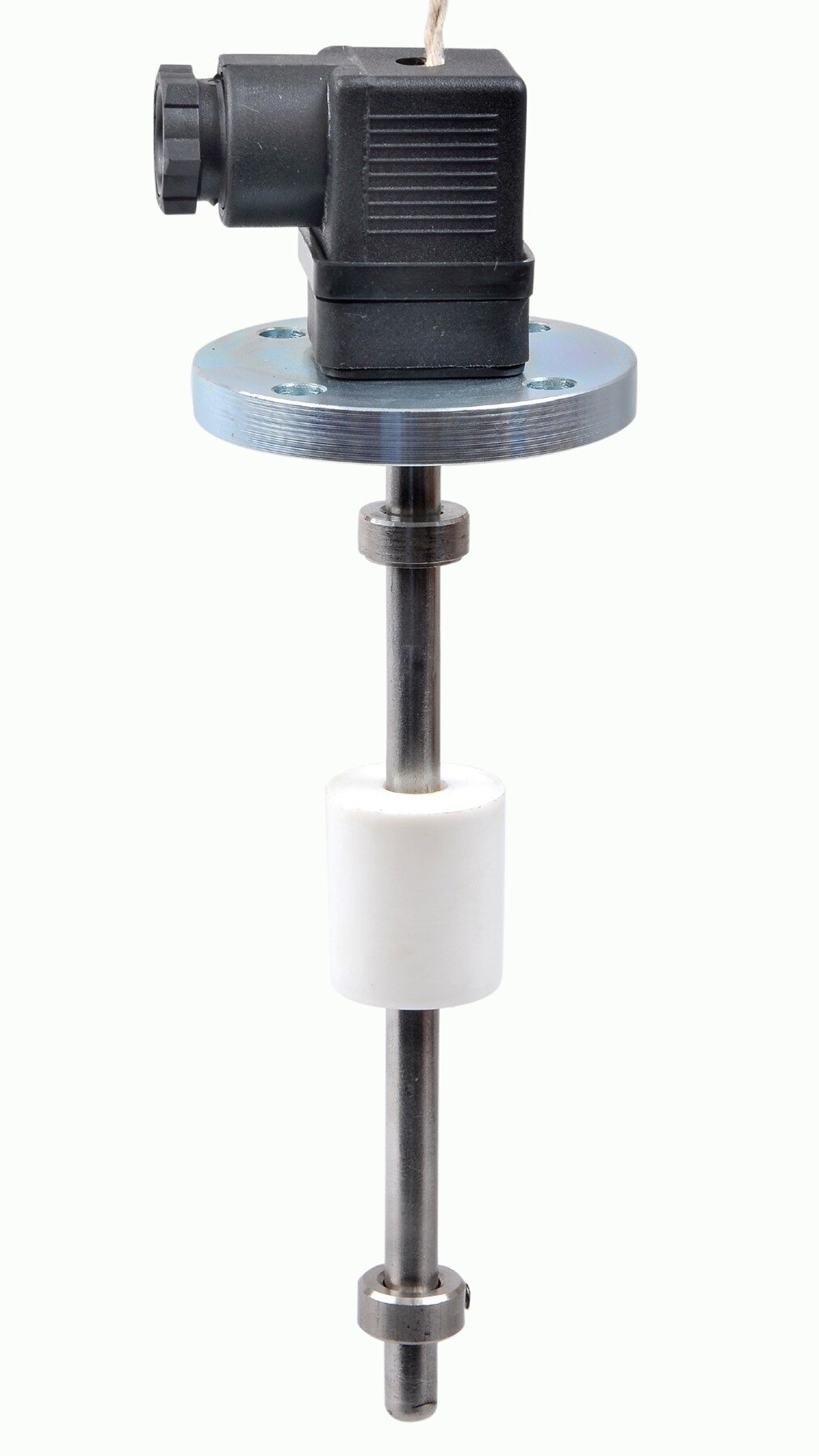
| Point float or side-mounted switch | Clean water, tanks, and simple sump start/stop duty | Confirm buoyancy, mounting position, agitation, ragging, and required start/stop levels |
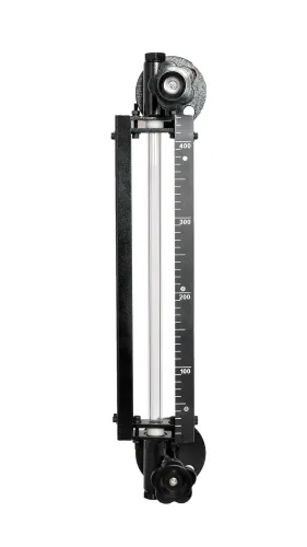
| Hydrostatic transmitter | Deep wells or tanks where continuous level and remote indication matter | Match wetted materials to the liquid and correct the zero reference for installation height |
| Ultrasonic transmitter | Open tanks with moderate temperature and a clear measurement path | Foam, vapour, condensation, turbulence, and a nearby inlet can create false readings |
| Radar transmitter | Vapour-prone, hot, or difficult process vessels needing continuous measurement | Check antenna compatibility, internal obstructions, foam behaviour, and process temperature |
For a sump pump, place the sensor away from the inlet jet, discharge turbulence, vortex, and sediment zone. A stilling tube, damping setting, or separate float location can stop local turbulence from creating nuisance starts.
A level controller with pump control should use a rising start level and a falling stop level. For a single fixed-speed pump, drive a contactor or starter; for variable flow, send a compatible run or speed command to the VFD.
Do not use a controller relay to switch motor current unless its motor rating permits it. Filpro Sensors Pvt Ltd can help you compare a magnetic or cable float arrangement against the sump geometry rather than choosing by name alone. Retain overload, dry-run, seal-leak, and high-temperature protection; a level signal cannot detect every pump failure.
Related products
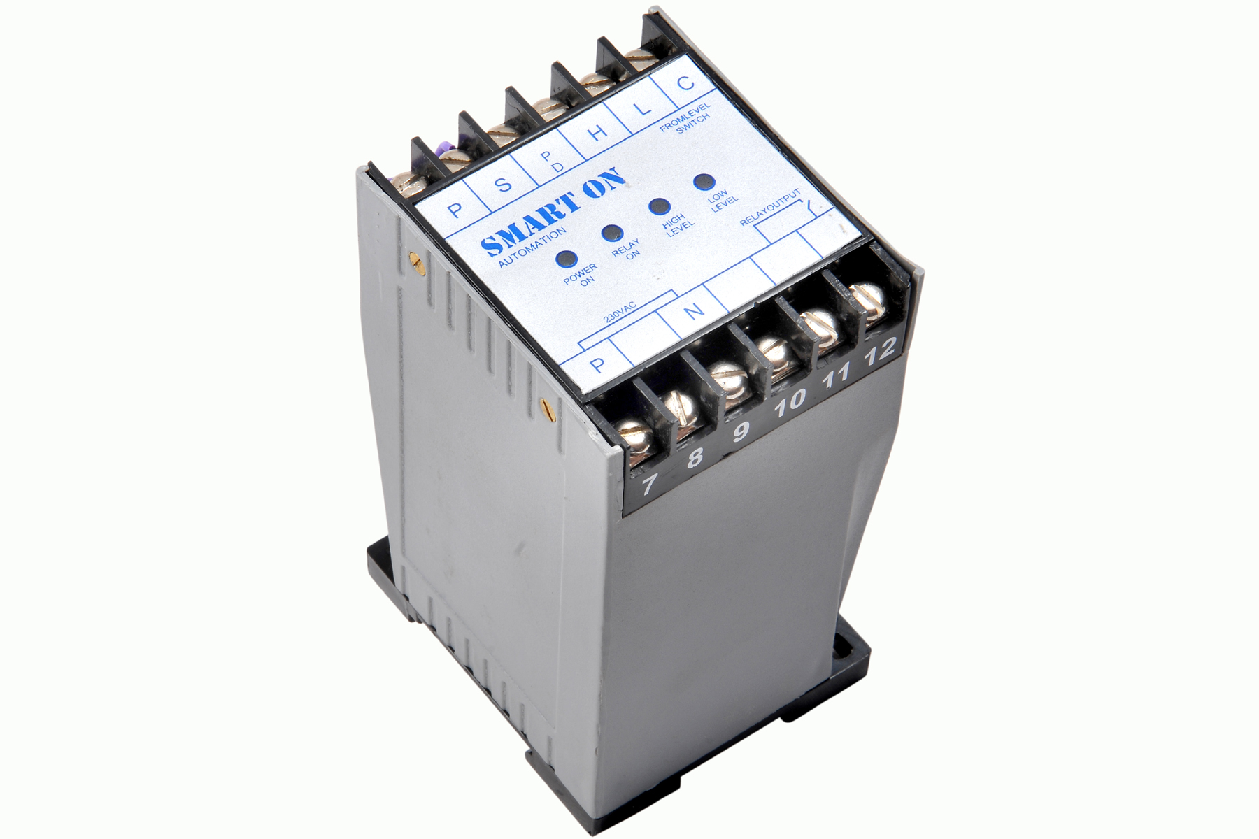 | Controller Filpro Sensors Pvt Ltd manufactures industrial Level Controller (Smart On) to automatically start & stop the pump. View product → |
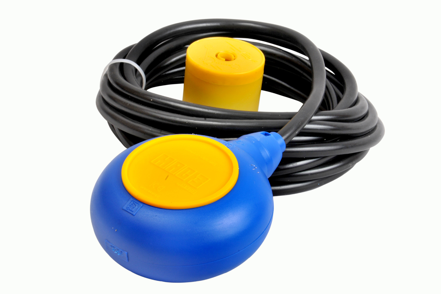 | Level Switch Cable Float Switch is mainly used for the automatic working of small pumps and cellar emptying pumps in liquids a little bit agitated. View product → |
Set up a sump float so it starts and stops safely
A level controller for sump pumps starts and stops safely only when the float’s movement matches the actual wet-well level. Mount it away from the inlet jet, pump discharge, vortex, and turbulent return flow; these can make the switch operate early or late.
Add a stilling tube, baffle, damping arrangement, or separate float bracket when the basin cannot provide calm water.
- Secure the float cable or guide so it cannot wrap around the pump, discharge pipe, ladder, or another float. Leave enough travel for switching, but not enough slack to reach an entangling point.
- Set the rising-level start point below the overflow elevation and above the normal inflow surge. Set the falling-level stop point above the pump’s minimum submergence; a low setting can create a vortex, draw air, lose prime, or cause dry running.
- Keep a clear deadband between start and stop. Without it, surface movement around one threshold can repeatedly start the motor.
- Test the full cycle with clean water, then inspect the float for grease, rags, and solids that restrict movement or leave it latched after the level falls.
- Configure a level controller for automatic pumping with manual-off-automatic selection, but keep motor overload, high-temperature, seal-leak, and low-level protections active outside the manual command path.
For two pumps, alternate the lead pump after each completed cycle and start the lag pump at a higher level. Alternation balances wear; it does not replace independent protection against a shared failed sensor, panel, power supply, or blocked discharge.
Add protection, multiple-pump logic and a commissioning test
A level controller for pump automation needs protections that remain active when the selector is in manual. Manual operation helps during commissioning and maintenance, but it can bypass normal level interlocks. Retain separate or hardwired protection for:
- Motor overload and short-circuit faults
- Motor winding temperature
- Mechanical-seal leakage
- Low level or dry running, where the pump requires it
A low-level stop alone does not prove dry-run protection. A blocked suction, lost prime, vapour formation or failed level sensor can leave the pump running; add motor-current, discharge-pressure, flow, pump-temperature or seal-monitoring protection that suits the equipment.
For multiple pumps, use lead-lag logic rather than starting every pump at once. The level controller pump control system should alternate the lead pump after each completed cycle, start the lag pump when level continues rising, and transfer duty when the lead pump trips.
Add a minimum run time or anti-short-cycle delay to prevent rapid starts in a turbulent sump or narrow deadband.
Commission the level controller for pump control under realistic conditions, not only with a dry signal:
- Raise the liquid to confirm the correct pump starts at the start threshold.
- Lower it and verify every pump stops at the stop threshold.
- Simulate a failed lead pump and confirm lag-pump takeover.
- Test overload, dry-run and sensor-fault trips separately.
- Repeat the test with actual inflow and discharge conditions; a pump may stop late, or level may keep rising after startup.
Record setpoints, delays, alarms and observed response times.
Frequently asked questions
How does a level controller start and stop a pump?
The sensor detects a level change, the controller applies its programmed start or stop logic, and the starter energises or disconnects the motor.
Which sensing method suits automatic pump control?
Use a float switch for straightforward point-level control; choose a continuous 4–20 mA transmitter when you need measured level, adjustable setpoints or tighter process control.
How should you set up a sump float switch?
Install the float at defined start and stop heights, provide enough separation between those points, and verify that the float moves freely without fouling the sump or pump.
What should you test before commissioning a pump control system?
Test sensor operation, start and stop levels, manual and automatic modes, overload protection, alarms, emergency stop, pump rotation and multi-pump sequencing.