Start by defining whether the system fills or drains the tank, then select switching points, a sensor, and a safe motor-control arrangement. By the end, you will have a wiring checklist, commissioning sequence, and record of settings that can be handed to a qualified electrician or maintenance team.
Key takeaways
- Define start and stop levels before selecting the controller.
- Match the sensor to the tank liquid, temperature, pressure, and installation conditions.
- Place overload, short-circuit, dry-run, and overflow protections in the control scheme.
- Test every alarm and switching point with the tank at real operating levels.
Define the control sequence and check the tank before buying parts
Before an automatic tank level controller setup, define the controlled action and operating limits. For filling, the pump or inlet valve starts at the low-level point and stops at the high-level point; for draining, that sequence reverses.
1. Choose two separate switching points, or one float with enough mechanical travel and hysteresis to create them. Set the separation from the tank’s usable volume, expected inflow, pump flow rate, minimum pump run time, valve response, and surface-wave movement. Close setpoints cause rapid cycling; wide setpoints can create unacceptable pressure or supply variation.
This separation is a process-design decision, not a universal automatic tank level controller value.
2. Record the tank’s liquid depth and usable volume before selecting a sensor. Check the wall thickness, nozzle and access-opening sizes, internal braces, ladders, inlet pipe, agitators, and pump hardware. A float must move freely and remain clear of turbulence, fouling, and obstructions; a stilling tube or protective cage must not trap it.
3. Obtain the controller’s nameplate voltage, phase, input type, output type, relay contact rating, and enclosure rating. Obtain the motor’s voltage, phase, full-load current, listed starting current, and overload-relay range. Match the relay to starting current; a larger pump normally needs a contactor and overload protection rather than direct switching.
4. Have a qualified electrician confirm cable sizes, protective devices, isolation, earthing, and local electrical-code requirements before installation.
Choose and position the sensor for the tank’s actual conditions
Choose the sensor and mounting arrangement to match the tank’s liquid, geometry, and operating conditions; that choice determines whether a liquid level controller for tanks switches reliably.
| Sensor | Suitable arrangement | Check before installation |
|---|---|---|
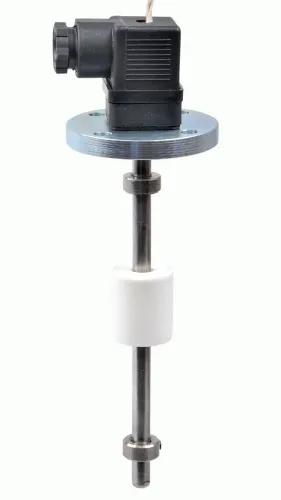
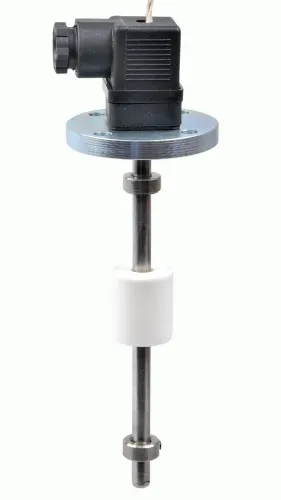
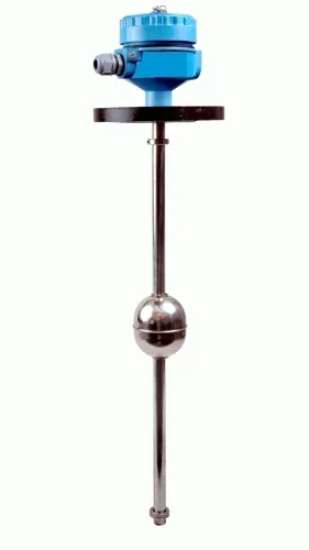
| Magnetic float switch | Clean water, with defined high and low positions | Mounting opening, float travel, orientation, and switching points |
| Cable float switch | Deep tank requiring long vertical travel | Cable length, attachment, counterweight, and entanglement risk |
| Side-mounted level switch | Fixed point on a tank wall | Nozzle size, wall thickness, temperature, pressure, and chemical compatibility |
| Conductive probes | Conductive liquids with a common or reference return | Conductivity and clean electrode surfaces |
A float is a point switch, not a continuous level transmitter. Keep it away from the inlet stream, pump suction, ladder, wall, and deposits; add a stilling tube or protective cage only when the float remains free to move.
For an automatic level controller for water tanks, do not use conductive probes with deionized water. Foam, oil films, mineral scale, or coating can insulate the electrodes and cause missed switching unless the liquid provides a reliable return path.
Ultrasonic sensors need a clear acoustic path, a configured blanking zone, and protection from foam, vapor, condensation, braces, agitators, sloped roofs, and turbulent filling. Never mount one directly above the inlet.
For hydrostatic sensors, check the pressure reference: open tanks use atmospheric reference, while closed tanks require the transmitter to account for gas pressure. Protect vented cables from moisture and damage.
Wire the controller, sensor, starter, and protections in the correct order
Automatic tank level controller wiring starts with the manufacturer’s terminal drawing, not a guessed terminal pattern. Confirm whether the unit is an integrated controller, a float switch, a powered output, or a dry relay contact; these functions are not interchangeable.
1. Isolate and lock out power. Wire the supply isolator to the protective device, then connect that device to the controller’s supply terminals: L and N, or L1, L2, and L3. Connect protective earth to the controller earth terminal, enclosure, motor frame, and tank equipment as specified.
2. Identify the sensor common or reference terminal, then connect the float contacts to the marked low-level and high-level inputs. Use the manufacturer-approved two-point float arrangement; do not assume a float’s wire order. Confirm which level starts filling and which level stops it.
3. Identify relay COM, NO, and NC, and record whether each contact is open or closed when the relay is de-energized. Connect the relay output to the contactor coil through the manual/automatic selector and the overload relay’s auxiliary contact. Wire any alarm output to its specified load or annunciator.
4. Connect the contactor’s main contacts to the motor, and provide overload protection sized to the motor nameplate. Keep sensor and 4–20 mA conductors separate from motor, solenoid, and variable-frequency-drive cables; install the approved diode, snubber, or surge suppressor across each inductive coil.
A small pump can switch directly only when voltage, current, utilization category, and starting capability cover its inrush. For a 2-wire loop-powered transmitter, check supply, polarity, loop load, and input type before wiring; it does not wire like a 3-wire voltage-output sensor.
Configure start, stop, dry-run, overflow, and sensor-failure behaviour
Configure the automatic tank level controller around two separate operating points: filling starts at low level and stops at high level; draining starts at high level and stops at low level. The physical gap between those points is the main protection against relay and pump chatter.
1. Set the low and high signals for the required direction. Confirm whether each float or probe input is normally open or normally closed. Also record whether the output relay is energised during a run or energised only during a safe stop; a reversed assumption can start a pump when you expect it to stop.
2. Add a start delay, minimum run time, or anti-cycle delay only within the pump manufacturer’s limits. Do not use timing to compensate for switching points that are too close together. A liquid level controller for tanks needs adequate low-to-high separation.
3. Wire low-level dry-run protection as a separate permissive. It must stop the pump when the source tank or sump is empty. Add a separate high-level cutoff when overflow could damage equipment or property; use an independent float, input, or hardwired trip when one failed sensor could cause a serious consequence.
4. Define the fault response before commissioning. A broken probe wire, lost 4–20 mA signal, or failed sensor supply can stop filling, stop the pump, raise an alarm, continue draining, or transfer control to a backup switch.
Use a normally closed, de-energise-to-trip circuit when power loss must produce a safer state, then verify that action against the controller’s actual relay logic. Wet-test both operating points and simulate each sensor fault.
Commission the system at real levels and document the final settings
Prove an automatic tank level controller for water tanks with a live wet test, not by moving a software setpoint alone. This automatic tank level controller setup is complete only when the equipment response, fault response, and final settings are recorded.
1. Isolate power and inspect every termination, earth connection, cable gland, enclosure seal, overload setting, and manual/automatic selector position. Correct loose conductors, damaged seals, or an incorrect overload before energising.
2. Restore controller power with the pump isolated. Check the supply voltage, sensor status, relay indication, alarm state, and displayed level.
3. Fill or drain the tank to the actual low operating point. For a filling system, confirm that the pump or valve starts at low level and stops at high level; for a draining system, confirm the reverse sequence.
4. Watch the physical pump or valve, not only the controller display. A reversed relay, float orientation, or motor connection can show a plausible level while changing state in the wrong direction.
5. Compare the displayed level with a tape measurement or calibrated reference. Record the difference and correct the installation if it exceeds the permitted accuracy.
6. Simulate a broken float wire, failed probe, lost 4–20 mA loop, overload trip, and power interruption. Record whether the system reaches the intended safe state, such as stopping filling, preventing dry running, raising an alarm, or transferring to backup control.
7. Observe one complete cycle for rapid switching, inlet turbulence, and insufficient pump run time. Record the controller model and serial number, sensor type, terminal drawing revision, supply voltage, motor current, overload setting, setpoints, delays, relay normal state, alarm action, cable routes, and test results.
For terminal questions, ask Filpro Sensors Pvt Ltd for the exact sensor-compatibility and wiring document for the selected controller, rather than copying a generic diagram.
Related products
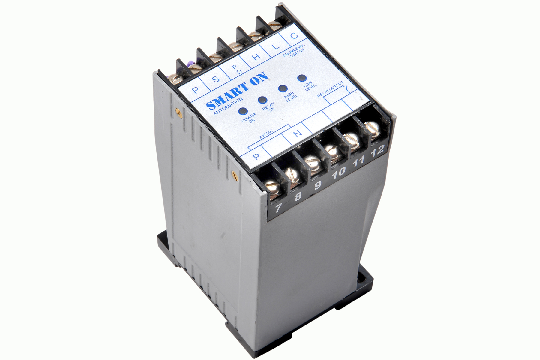 | Controller Filpro Sensors Pvt Ltd manufactures industrial Level Controller (Smart On) to automatically start & stop the pump. View product → |
 | Level Switch Filpro offers most reliable, cost effective Side Mounted Level Switch for point level sensing. View product → |
Frequently asked questions
What should you define before buying an automatic tank level controller?
Define whether the system fills or drains the tank, then set the low and high operating levels, pump or valve action, and protection limits.
How do you choose and position a tank level sensor?
Match the sensor to the liquid and tank conditions, then position it away from turbulence, inlet flow, foam, sludge, and moving equipment.
What is the correct order for automatic tank level controller wiring?
Route the supply through isolation and protective devices, connect the controller and sensor, then use the controller output to operate the starter or valve circuit.
How do you commission an automatic level controller for water tanks?
Fill or drain the tank through the actual operating range, verify start and stop points, test dry-run and overflow responses, and record the final settings.