A level controller wiring diagram combines low-voltage sensing, relay logic and motor power, so a terminal that looks similar may perform a completely different job. By the end, you will be able to identify the signal architecture, trace each conductor, interpret NO and NC contacts, and verify whether the circuit starts a pump to fill or empty a tank.
Key takeaways
- Classify the signal type from the terminals and power path first.
- Trace control power separately from motor power.
- Use NO and NC labels with the fill or empty action.
- Check signal limits against commissioning records before energising the pump.
Classify the signal architecture before following any wire
Determine the architecture from the terminals and power path before tracing any wire: a level controller wiring diagram will show one of four signal types.
1. A 2-wire loop-powered transmitter uses the same pair for supply and 4–20 mA signal. The loop needs an external supply, and 4 mA represents the configured lower range, not necessarily an empty tank.
2. A 3-wire or 4-wire powered transmitter has separate power and signal conductors. In a 4-wire instrument, read the supply circuit and analog-output circuit separately; an active output supplies loop current, while a passive output requires an external loop supply.
3. A discrete level switch uses an on/off contact or solid-state signal from a float, probe, or reed device. Do not connect it as though it were a 4–20 mA transmitter.
4. A controller with relay outputs switches contacts for a pump or alarm. Check whether the output is a dry contact, transistor, or solid-state device, then confirm its voltage, current, polarity, and leakage limits.
Read relay contacts in the de-energized state: normally open and normally closed describe that state, while fail-high or fail-low determines the selected response to lost power or signal. Wiring alone does not reveal range, damping, calibration, alarm direction, or relay delay; verify those in commissioning records.
Read the terminals one circuit at a time
Read a level controller wiring diagram one circuit at a time: identify the supply circuit, trace the sensor input, then follow the output to the contactor.
- Supply terminals, marked L and N for AC or + and − for DC, power the controller. Confirm the voltage on the nameplate before connecting anything.
- Sensor terminals receive the float switch, probe, or transmitter signal. On a four-wire instrument, keep these sensor terminals separate from the instrument’s power terminals.
- Common, marked COM or C, is not automatically a supply negative. It can be the sensor reference or the shared terminal for a relay contact, so trace the printed circuit around it.
- Output terminals carry the control signal. A relay output normally provides COM, NO, and NC contacts; a dry contact needs an external control voltage. A transistor output instead requires the stated polarity, load limit, and voltage.
- Contactor terminals connect the controller’s output circuit to the contactor coil, not directly to the pump motor. The contactor then switches the motor’s higher-current supply through its main contacts.
For a 2-wire, 4–20 mA transmitter, the supply, transmitter, and receiving input form one series loop. Do not wire it across a voltage source like a four-wire instrument. Check the diagram and data sheet before assuming whether an output is active or passive.
Identify symbols and separate control power from motor power
In a level controller wiring diagram, recognise symbols by their function, then mark the voltage and current path. Sensor and controller wiring usually forms the low-voltage control circuit; the contactor and motor path carries motor current. A four-wire instrument can also show separate supply and analog-output terminals, with an active or passive output.
- Float switch: moving arm or buoyant body operating an NO or NC contact.
- Magnetic reed switch: contact beside a magnet, often inside a tube.
- Electrode probes: several vertical lines entering the tank.
- Relay: coil symbol paired with changeover contacts.
- Contactor: relay-like coil with heavier main contacts.
- Overload relay: motor protection block in series with the motor.
- Motor: circle marked M, sometimes with three-phase terminals.
- Fuse: small rectangle or narrow link in series.
- Earth: three descending horizontal lines.
Trace the control path from sensor input to controller relay, through the relay contact and contactor coil, then back to the control supply. Trace motor power separately: supply, fuse, contactor main contacts, overload, and motor.
A relay output may be a dry contact, so provide an external control voltage rather than assuming the controller powers the pump.
Read NO and NC from the relay’s de-energized state. Float orientation and configuration determine whether rising level opens or closes the circuit; verify that direction in the data sheet.
Trace the level signal through the relay to the pump
Read a level controller wiring diagram in the direction the command travels: sensor, input terminal, relay coil, relay contact, contactor coil, then pump. The pump’s motor current should not pass through a small controller relay unless the contact rating explicitly permits it.
1. Start at the sensor terminals. Two wires ending at one switch symbol usually indicate a simple two-wire float or a two-wire loop-powered transmitter. For a transmitter, the same pair carries power and measurement current; for a float, it only opens or closes the control circuit.
2. Three float wires usually identify a common, normally open and normally closed contact. Trace the common to the controller input, then see which return wire reaches the relay logic. The controller uses one contact for rising-level start and the other for falling-level stop or fail-safe operation.
3. Multi-level floats show separate switching points, separate input terminals, or several float symbols on one tank. Trace each return independently; labels such as LOW, HIGH and HIGH-HIGH reveal which level starts, stops or alarms the pump.
4. Find the relay coil, then follow its contact from COM to NO or NC. Read that contact with the coil de-energized: NO is open and NC is closed. A fail-high or fail-low strategy determines which path remains safe after lost power or signal.
5. Continue from the selected contact to the contactor coil and overload auxiliary contact. That chain proves the pump command; the motor power circuit remains a separate path. The diagram cannot confirm relay delay, calibration or alarm direction, so check commissioning records.
Interpret NO, NC and fill-versus-empty logic correctly
In a level controller wiring diagram, NO and NC describe the relay’s de-energized state: NO is open; NC is closed. The drawn contact is a reference, not its running state. Energising the coil reverses it, while a fail-high or fail-low strategy selects the response to lost power or signal.
A float or probe can switch on rising or falling level; verify that direction in the data sheet or setup menu.
| Function | Level action | Result |
|---|---|---|
| Fill control | Low start, high stop | Replenish tank |
| Emptying control | High start, low stop | Transfer liquid out |
| Dry-run protection | Low-level trip | Stop the pump |
| Overflow protection | High or high-high trip | Stop inlet equipment |
| Alarm | High, low, or fault condition | Annunciate the condition |
- Match the intended action to the configured setpoints, not merely the NO or NC symbol.
- Confirm whether the output is a dry contact requiring an external voltage circuit, or a transistor/solid-state output with specified polarity and leakage limits.
- Check the configured range, damping, empty/full calibration, alarm direction, and relay delay in commissioning records; identical wiring can produce different running behaviour.
Check the diagram against signal limits and commissioning records
Before energising, verify the level controller wiring diagram against the instrument data sheet, purchase specification, and commissioning records. The drawing shows connections, not configured behaviour: identical terminals can produce different results after changing range, damping, calibration, alarm direction, or relay delay.
1. Confirm the supply voltage and polarity at the controller, transmitter, barrier, and isolator. Check that the 4–20 mA input range, output limits, and active or passive loop arrangement match the connected equipment.
2. Compare the configured empty and full points, engineering units, damping time, alarm direction, and relay delay with the commissioning record. A correct wire cannot correct an incorrect parameter.
3. Check relay contact ratings against the load or contactor coil, and verify the intended fail-high or fail-low state during power and signal loss.
4. For an intrinsically safe circuit, match voltage, current, power, capacitance, inductance, grounding, cable separation, and barrier entity parameters. Nominally using 4–20 mA does not remove those limits.
5. Record continuity, insulation, polarity, and terminal torque results before applying power.
Ask for a manufacturer’s wiring review when the architecture is unclear, records conflict with the drawing, a loop uses a barrier, or a replacement instrument has different active/passive output requirements. Filpro Sensors Pvt Ltd can review the proposed connections against the selected instrument and its commissioning conditions before a wiring mistake reaches the pump.
Related products
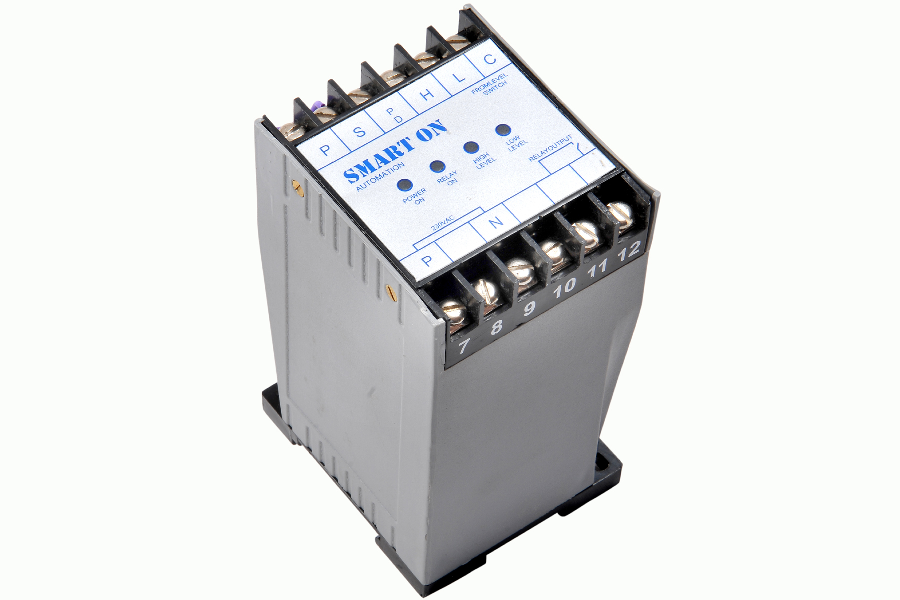 | Controller Filpro Sensors Pvt Ltd manufactures industrial Level Controller (Smart On) to automatically start & stop the pump. View product → |
 | Level Switch Filpro offers most reliable, cost effective Side Mounted Level Switch for point level sensing. View product → |
Frequently asked questions
How do you classify a level controller wiring diagram?
Identify the terminals and power path to determine whether the controller uses a switch, electrode probe, analogue signal or digital signal.
How do you trace a level signal to the pump?
Follow the signal into the controller, through the relay contacts, and onward to the pump contactor or starter circuit.
What do NO and NC mean on a level controller wiring diagram?
NO means normally open and NC means normally closed; interpret each contact alongside whether the system fills or empties the tank.
How do you check a wiring diagram before commissioning?
Compare the diagram with the controller’s signal limits, terminal ratings and commissioning records before energising the circuit.
Related product
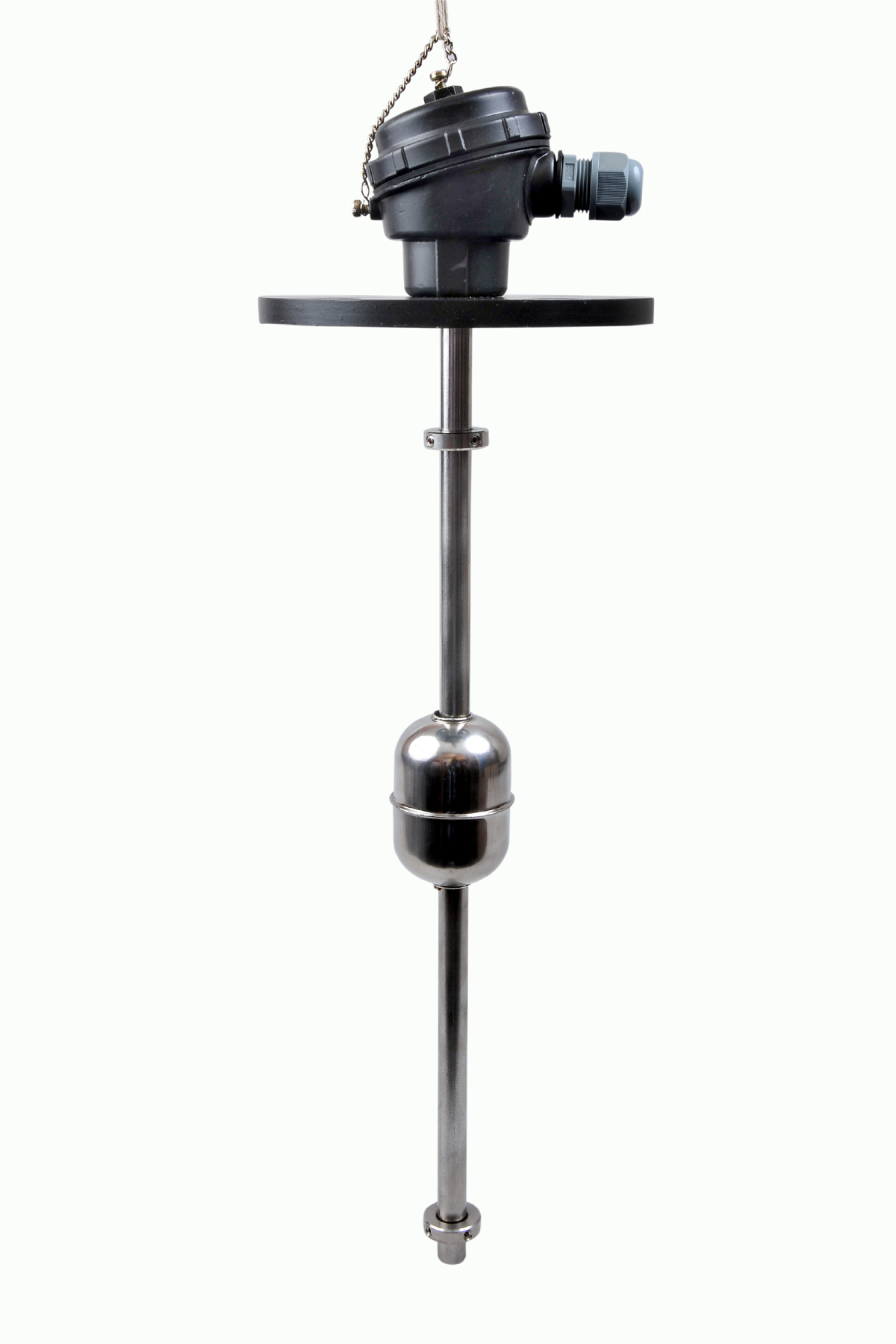 | Level Switch The Magnetic Level Switch consists of the non-abrasive float carrying permanent magnet and non-ferrous stem carrying one. View product → |