Choose the measurement principle only after you define the tank geometry, liquid behaviour, operating envelope and control task. By the end, you will be able to specify the measuring span, reject unsuitable technologies, and request an instrument that integrates correctly with your PLC, DCS, SCADA system or pump controller.
Key takeaways
- Define the required measurement span from the tank’s usable volume.
- Check foam, vapour, density, pressure and internal obstructions before choosing technology.
- Specify output signal, control action and hazardous-area requirements together.
- Put process data, connection details and testing requirements into the purchase specification.
Start with the measurement task, not the transmitter catalogue
Choose an industrial level transmitter for tanks by matching the measurement principle to the tank and liquid, not by starting with catalogue range.
| Principle | Best fit | Main limitation |
|---|---|---|
| Non-contact radar | Many open or closed process tanks; useful with pressure, temperature, vapour and moderate turbulence | Weak echoes from low-dielectric liquids, small surfaces, obstructions, buildup or a poor nozzle |
| Guided-wave radar (GWR) | Tanks where a probe is practical and foam, vapour or changing gas conditions defeat ultrasonic measurement | Probe installation, coating and mechanical clearance need checking |
| Hydrostatic differential pressure (DP) | Economical liquid service with stable density | Measures pressure head, so density changes appear as level changes |
| Ultrasonic | Open tanks with a clean, calm gas space and predictable temperature | Vapour, condensation, foam, dust, turbulence and temperature gradients can cause lost or unstable echoes |
For a closed tank, DP uses the high side for liquid pressure and the low side for vapour-space pressure. A plugged impulse line, trapped gas, unequal condensation or a wet reference leg can create a false level; remote diaphragm seals reduce plugging and freezing risk but add capillary temperature error and slower response.
Treat radar’s stated maximum distance as a starting point, not proof of performance. Confirm echo margin at the liquid’s dielectric constant, surface condition and antenna location. Define the usable level span from the reference point, zero elevation and upper range value, then subtract antenna or probe dead zones.
Include alarm, trip and overfill margins, plus the consequence of falling below the minimum measurable distance.
Match the transmitter to tank geometry and the usable measuring span
Tank geometry and mounting location determine the transmitter’s usable span: measure from the actual reference point to the highest controllable level, then subtract inactive zones and reserve alarm, trip and overfill margins.
- Vertical cylindrical tanks: A top-mounted transmitter can cover most of the height, but keep the antenna or probe clear of the wall and internal fittings.
- Horizontal cylindrical tanks: Level does not change linearly with volume, so configure the transmitter for level and use a tank strapping table or conversion function for volume.
- Conical tanks: The lower section produces a large level change from a small volume; place the zero reference at the true outlet or minimum operating level.
- Rectangular tanks: Check the mounting side and internal width because nearby walls can distort non-contact signals.
A top-mounted instrument measures downward from the nozzle, not upward from the tank floor. The nozzle height, probe or antenna dead zone, and the lowest measurable distance can therefore leave part of the tank unmeasurable.
A nozzle that extends into the vessel, or a location above an agitator, coil or ladder, can create false echoes or unstable readings.
Before ordering, document:
- Zero elevation and reference point
- Upper range value at the maximum operating level
- Minimum and maximum operating levels
- Alarm, trip and overfill margins
- Nozzle length and the transmitter’s blocked distance
For hydrostatic measurement, locate the pressure tap at the defined zero and include liquid density changes in the range calculation. Configure the output span around usable measurement, not total shell height.
Account for foam, vapour, density, pressure and internal obstructions
A technically suitable industrial level transmitter for tanks can still give an unreliable reading when the process changes the signal path or the pressure-to-level relationship. Check foam, vapour, density, tank pressure, turbulence, condensation and obstructions before accepting the stated measuring range.
| Condition | What goes wrong | What to check |
|---|---|---|
| Foam or vapour | Ultrasonic sound is attenuated or reflected by foam, vapour and condensation; the echo can disappear or wander. | Use radar or guided-wave radar when gas-space conditions vary. |
| Changing density | A hydrostatic DP transmitter converts pressure head into level using density. Temperature, concentration or recipe changes then create level error without any transmitter fault. | Confirm density across the full batch and operating-temperature range. |
| Pressure changes | On a closed tank, incorrect vapour-space compensation makes pressure look like liquid level. | Connect the high side to liquid pressure and the low side to vapour pressure; inspect impulse lines and reference legs. |
| Agitation or turbulence | A moving surface reduces echo strength and makes the indicated level fluctuate. | Use suitable damping, an installation position away from inlets, or GWR where a probe is practical. |
| Obstructions or buildup | Nozzles, heating coils, ladders, agitators and deposits can create false radar echoes or weaken the return. | Check the antenna sightline, nozzle design and buildup risk rather than relying on maximum range. |
A plugged impulse line, trapped gas or unequal condensation can shift a DP reading. Remote diaphragm seals reduce plugging and freezing, but long capillaries add temperature error and slow response.
For radar, low-dielectric liquid and a small effective surface can leave too little echo margin. Specify the actual liquid, vapour, temperature, pressure and obstruction layout to the supplier.
Specify the signal, control function and hazardous-area installation
Choose continuous measurement when the control system needs the actual level, not merely a full or empty status. Choose point-level switching when the decision is discrete, such as stopping a pump at low level or opening an overfill alarm.
| Option | Signal and function | Best fit |
|---|---|---|
| 4–20 mA | Continuous level for a PLC, DCS or display; HART adds configuration and diagnostic data over the same pair | Long cable runs, analog control loops and alarm limits calculated in the control system |
| Modbus RTU over RS-485 | Digital level and diagnostic values from multiple instruments | Addressable networks where the PLC or SCADA system supports Modbus and wiring effort is acceptable |
| Relay or transistor switch | Point-level status at a fixed setpoint | Independent high-high, low-low, pump start/stop or permissive logic; not a substitute for continuous inventory data |
Specify the control consequence, not just the signal. State whether the transmitter must provide total level, interface level or both, and define how an interface reading will be validated when the boundary is emulsified or moving.
For a hazardous area, identify the zone, gas or dust group, and temperature class before choosing the enclosure and wiring method. Confirm the transmitter’s IEC 60079 protection method, such as Ex ia intrinsic safety or Ex d flameproof construction, then match barriers, isolators, cable glands, grounding and entity parameters to it.
Do not connect an intrinsically safe loop directly to ordinary control-system terminals without checking the segregation and interface design.
If the signal forms part of a safety instrumented function, specify the required SIL, proof-test interval, response time and voting architecture; “SIL capable” alone does not validate the installed loop.
Turn the selection into a complete purchase specification
Give suppliers a process-and-installation data sheet, not only the required range and output. State whether you want a complete industrial level transmitter for tanks, including process connection, probe or antenna, remote seal, cable entry, mounting hardware and configuration.
- Measurement: total level, interface level or both; continuous measurement or point switching; required accuracy, repeatability, resolution and response time.
- Technology: preferred principle, or permission to propose non-contact radar, guided-wave radar, ultrasonic, float, capacitance or hydrostatic DP with a written reason.
- Tank drawing: nozzle size and height, internal diameter, roof shape, agitators, ladders, coils, inlet streams and the distance from the connection to the lowest and highest measured levels.
- Process data: liquid name, density range, dielectric properties for radar, viscosity, solids, emulsion behaviour, vapour, foam, condensation, turbulence, operating pressure and temperature.
- Mechanical limits: normal and excursion pressure, vacuum, steam-out or cleaning temperature, blocked-in heating exposure, wetted-material requirements and gasket specification.
- Installation: hazardous-area zone, gas or dust group, temperature class, equipment protection level, ambient temperature, protection concept, cable glands, barriers and intrinsic-safety entity parameters.
- Safety function: SIL target, SIF architecture, voting arrangement, proof-test interval, response time, dangerous failure rates and diagnostic coverage; “SIL capable” alone is not a specification.
- Deliverables: dimensional drawing, terminal plan, certificates, calibration record, configuration file, commissioning procedure and stated blind-zone and false-echo limits.
When comparing a proposal from Filpro Sensors Pvt Ltd, require these details for the complete assembly, not just the sensor body; remote seals, probes, antennas and electronics can have different limits.
Related products
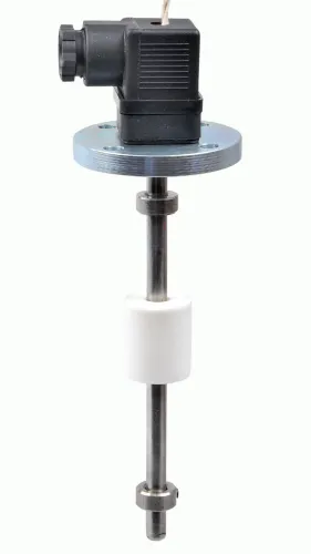
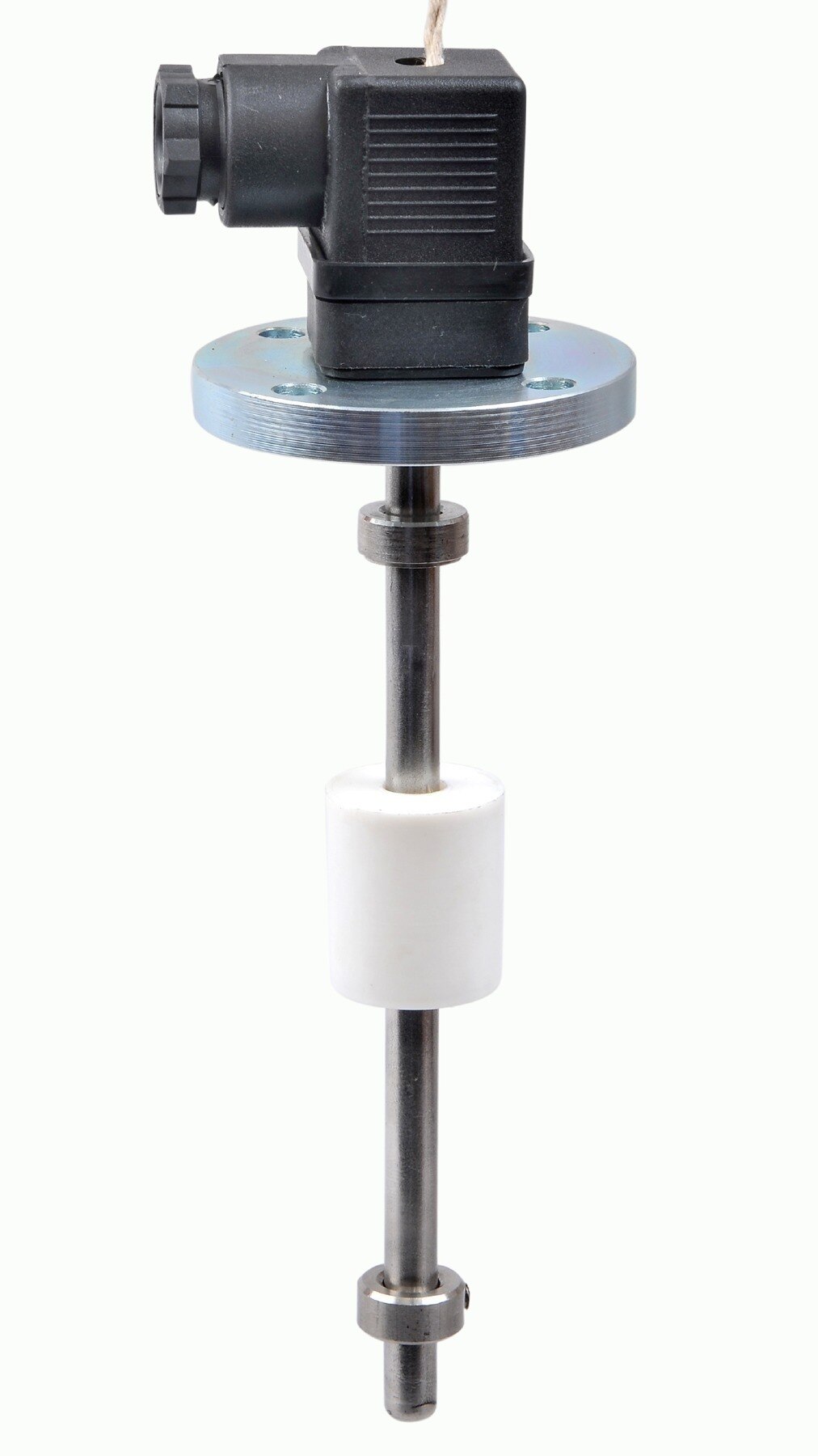
 | Level Sensor Atex approved Float Level Transmitter : Over All Length: 300mm to 5000mm Input: 16V DC to 30V DC Output: 4-20mA / 0-10V DC Resolution: 5mm / 10mm... View product → |
 | Level Transmitter Float Level Transmitters Are Ideal For Continuous Level Monitoring In Water, Diesel, Chemical And Oils For Accurate Level Measurement. View product → |
Frequently asked questions
What should you assess before comparing industrial level transmitters for tanks?
Define the measurement task first: required accuracy, measuring span, response time, alarm needs and whether you need continuous level or point detection.
How does tank geometry affect transmitter selection?
Review the tank’s height, diameter, shape, dead zones, nozzle position and usable measuring span. These details determine where the transmitter can be installed and which measurement principle will work.
Which liquid and process conditions matter when choosing a level transmitter?
Assess foam, vapour, density changes, pressure, temperature, turbulence, corrosive properties and internal obstructions because each condition can affect measurement reliability.
What electrical and installation details belong in the specification?
State the required output, such as 4–20 mA or a digital protocol, control function, power supply, process connection, enclosure protection and hazardous-area classification.
Related products
 | Level Transmitter Ultrasonic Level Sensor is a non-contact ultrasonic continuous level measurement product based on sound technology. View product → |
 | Level Transmitter Hydrostatic liquid level transducers and transmitters with flush diaphragm is designed fora wide variety of level measurement applications. View product → |
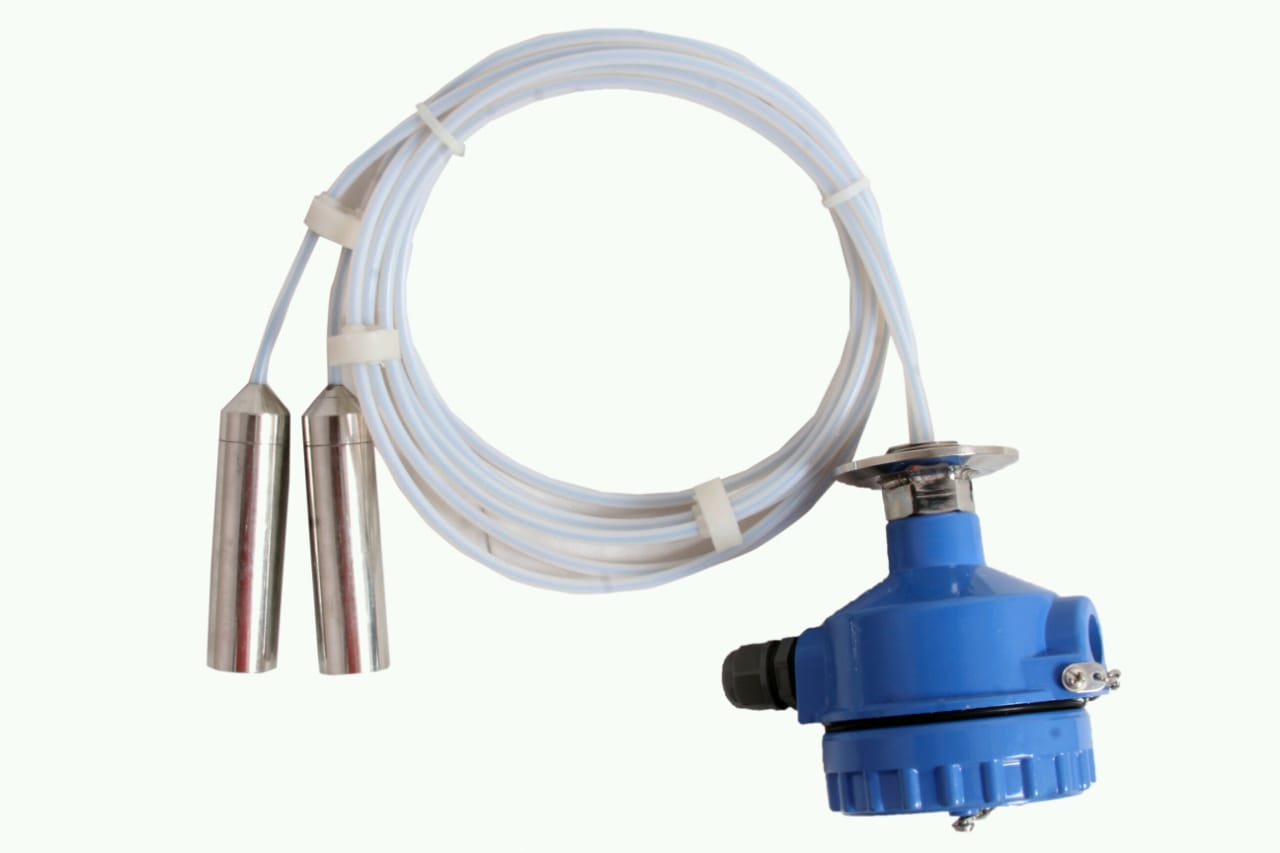 | Level Transmitter can be used for conductive as well as non conductive liquids. View product → |
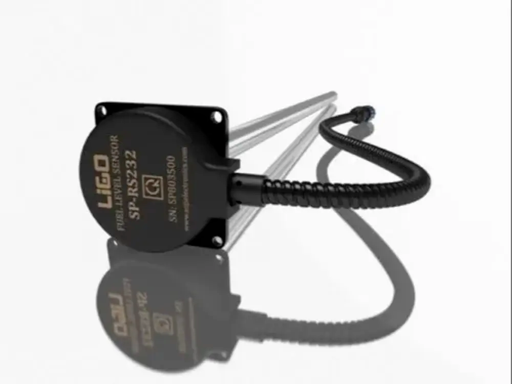 | Level Sensor Ligo fuel sensor for monitoring Diesel and Petrol level in vehicle fuel tanks and DG sets. View product → |