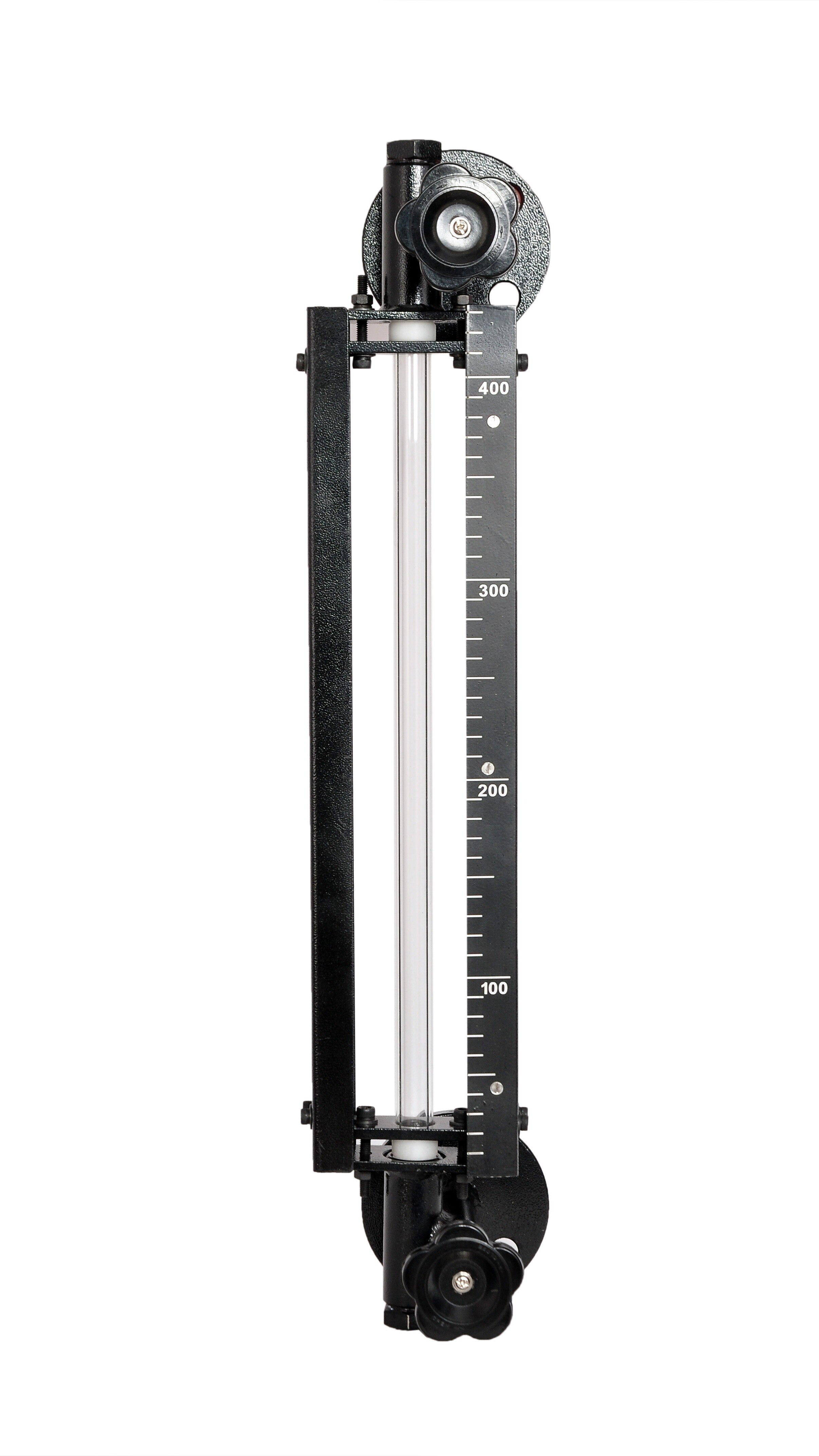
A replacement that fits the tank can still fail because it uses the wrong measurement principle, reference datum, signal, or wiring. By the end, you will be able to compare tank level sensor replacement options, check process and control-system compatibility, install the device safely, and prove that the displayed level and alarms are correct.
Key takeaways
- Define whether you need continuous level, volume, protection, or pump control.
- Match sensor technology to the liquid, tank geometry, temperature, and pressure.
- Verify process connection, probe length, enclosure, output, and wiring before removal.
- Record scaling, alarm limits, and control logic before commissioning the replacement.
Start with the measurement job and tank conditions
Define the measurement job before comparing tank level sensor replacement options. Decide whether you need continuous level, volume calculation, overfill protection, low-level protection, or a simple pump-start signal. A side-mounted point switch cannot replace a transmitter when the control system needs a live level value.
- Record the tank height, usable minimum and maximum levels, measurement datum, required accuracy, engineering units, output signal, alarm points, and control-system scaling.
- Record the process connection, nozzle diameter, insertion length, mounting thread or flange, available headroom, pressure, temperature, corrosion risk, and whether the tank is open or closed.
- Describe the liquid: density and its variation, viscosity, conductivity, solids, coating tendency, foam, vapour, turbulence, and agitator operation. These conditions separate hydrostatic, radar, guided-wave radar, ultrasonic, capacitance, magnetostrictive, float, displacer, and point-switch applications.
- Reject direct substitutions that ignore the physics. Hydrostatic pressure follows density, so blending or temperature changes can alter indicated level. Ultrasonic devices can lose an acoustic echo through foam, vapour, condensation, dust, or turbulence. Closed-tank differential pressure also needs high- and low-side connections; blocked impulse lines or a changing wet leg create errors.
- Before commissioning, match the replacement’s reference datum, orientation, empty point, full point, and tank height to the control system. Confirm the configured units, then test one known level or a credible simulation; a correct 4 mA signal can still represent the wrong level.
Choose a technology that suits the liquid and tank
Choose the measurement principle, not just a replacement with the same range. A hydrostatic or differential-pressure transmitter measures pressure head, so changing density from blending, temperature, concentration, or multiple liquid phases changes the indicated level. It is a poor geometric-level substitute in those conditions.
Also compare the process connection, reference datum, insertion length, pressure, temperature, agitation, foam, vapour space, and output.
| Option | Main dependency | Choose it when |
|---|---|---|
| Hydrostatic or differential pressure | Liquid density and pressure head | Density is stable and the tank has a suitable pressure connection |
| Non-contact radar | Microwave reflection | Foam, vapour, dust, or changing density rules out contact measurement |
| Guided-wave radar | Reflection along a probe | A defined probe path is practical and vapour or turbulence affects the surface |
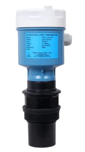
| Ultrasonic | Acoustic return path | The tank has a calm, clean, non-condensing vapour space |
| Capacitance or RF admittance | Dielectric properties and probe coating | Product composition and buildup remain predictable |
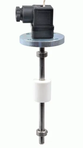
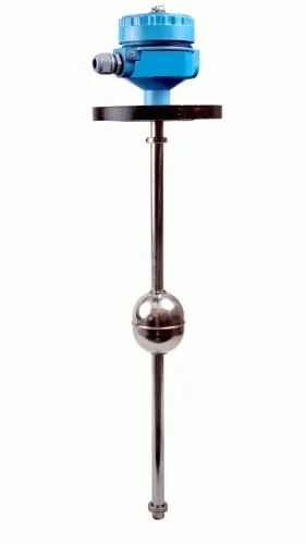
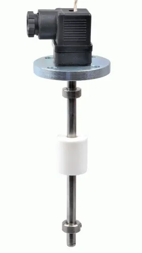
| Float, displacer, or magnetostrictive | Mechanical position or buoyancy | The liquid is clean enough for moving or immersed parts |
Ultrasonic sensors can lose their echo through foam, condensation, temperature gradients, dust, or turbulence. Capacitance probes need recalibration when the product, moisture level, conductive coating, or probe length changes. A point-level switch is not a substitute for continuous measurement when the control system needs an actual level trend.
During commissioning, match the replacement’s reference datum, empty and full points, orientation, and engineering units to the control-system scaling. A correct 4 mA signal can still represent the wrong tank level. Verify one known level or a credible simulation before accepting the tank level sensor replacement options.
Check the mechanical fit and replace the device safely
Verify the tank connection against the replacement drawing, not the old sensor’s appearance. Check nozzle diameter, mounting thread or flange standard, gasket material, insertion length, reference datum, headroom, and clearance from agitators, coils, ladders, and other internals. The probe must not touch the wall or obstruct an opening.
A matching connection does not prove electrical compatibility. Confirm the output type and control-system input, then check that a two-wire 4–20 mA loop has enough supply voltage after input, cable, barrier, isolator, and other voltage drops. Follow the new wiring diagram for shield bonding, protective earth, polarity, and hazardous-area barriers.
- Lock out electrical power and isolate the tank from connected equipment.
- Shut inlet and outlet valves, then drain or depressurise the tank when the process, pressure, or temperature makes removal unsafe.
- Confirm zero pressure and a safe temperature before loosening the old probe, switch, flange, or cable gland.
- Remove the device without forcing a seized thread; inspect the nozzle face, threads, flange, gasket seat, corrosion, and deposits.
- Fit the specified gasket and install the replacement to the manufacturer’s thread engagement or flange-bolt instructions. Do not rotate a probe into internal obstructions.
- Restore wiring, grounding, enclosure seals, and cable strain relief, then check for leaks.
- Power the instrument, verify the displayed level against the actual reference, and test the 4–20 mA loop, alarm points, or fieldbus diagnostics before returning the tank to service.
Match the output, control input, and tank level sensor wiring
Confirm compatibility by matching the replacement’s output protocol, terminal functions, power requirements, and scaling with the existing PLC, indicator, controller, or data logger. A 4–20 mA input is not interchangeable with a pulse, relay, IO-Link, or fieldbus input. HART communication rides on a 4–20 mA loop; it does not replace a suitable analog input.
- Read the old and new terminal diagrams. A two-wire loop-powered transmitter, three-wire sensor, four-wire transmitter, and separate switching output use different supply and signal circuits.
- Trace the tank level sensor wiring from the device to the input card. Confirm wire polarity, signal reference, shield termination, barriers, isolators, and any shared 0 V connection.
- Check loop voltage compliance for a two-wire transmitter. The DC supply must cover the transmitter’s minimum voltage plus voltage drops across the input load, cable, barriers, and other series devices.
- Compare the configured empty and full values, engineering units, measurement datum, and tank height. A correct 4 mA signal still indicates the wrong level if the sensor’s zero point or orientation differs.
Commission the replacement at a known level or with a credible signal simulator. Record the transmitter output and confirm that the control system displays the same level in the correct units.
Test the high- and low-level alarms separately; reversing polarity, floating the signal reference, or feeding external voltage into an output can damage equipment or create a false safe indication.
Preserve scaling, alarms, and control logic during commissioning
Prove the replacement by matching its reference datum and engineering units to the control system, then checking the reading at a known level or against a credible simulation.
A correct 4 mA signal can still indicate the wrong level if the transmitter’s zero point, full point, orientation, or configured tank height differs from the programmed scaling.
- Record the physical zero and full-level references, then compare them with the transmitter configuration and PLC or DCS range.
- Verify the displayed level at one measured liquid height; check two heights when the tank geometry or probe insertion differs from the old device.
- Treat tank level sensor wiring as a complete circuit. For a two-wire loop, confirm supply voltage remains above the transmitter’s minimum requirement plus drops across the input, cable, barriers, isolators, and other series devices.
- Check terminal functions before energising. A four-wire transmitter, three-wire sensor, and two-wire loop device do not share the same power and signal connections.
- With the control loop in manual or test mode, simulate low-low, high-high, and normal signals and record each alarm, interlock, and output response.
- Return automatic control only after confirming the displayed engineering value, alarm reset behaviour, controller action, and final control element response.
Ask Filpro Sensors Pvt Ltd for the proposed device’s terminal diagram, datum reference, and calibration range so you can compare them with the approved loop drawings before commissioning. Never accept a compatible connector as proof of compatible scaling or safe control operation.
Related products
 | Level Sensor Atex approved Float Level Transmitter : Over All Length: 300mm to 5000mm Input: 16V DC to 30V DC Output: 4-20mA / 0-10V DC Resolution: 5mm / 10mm... View product → |
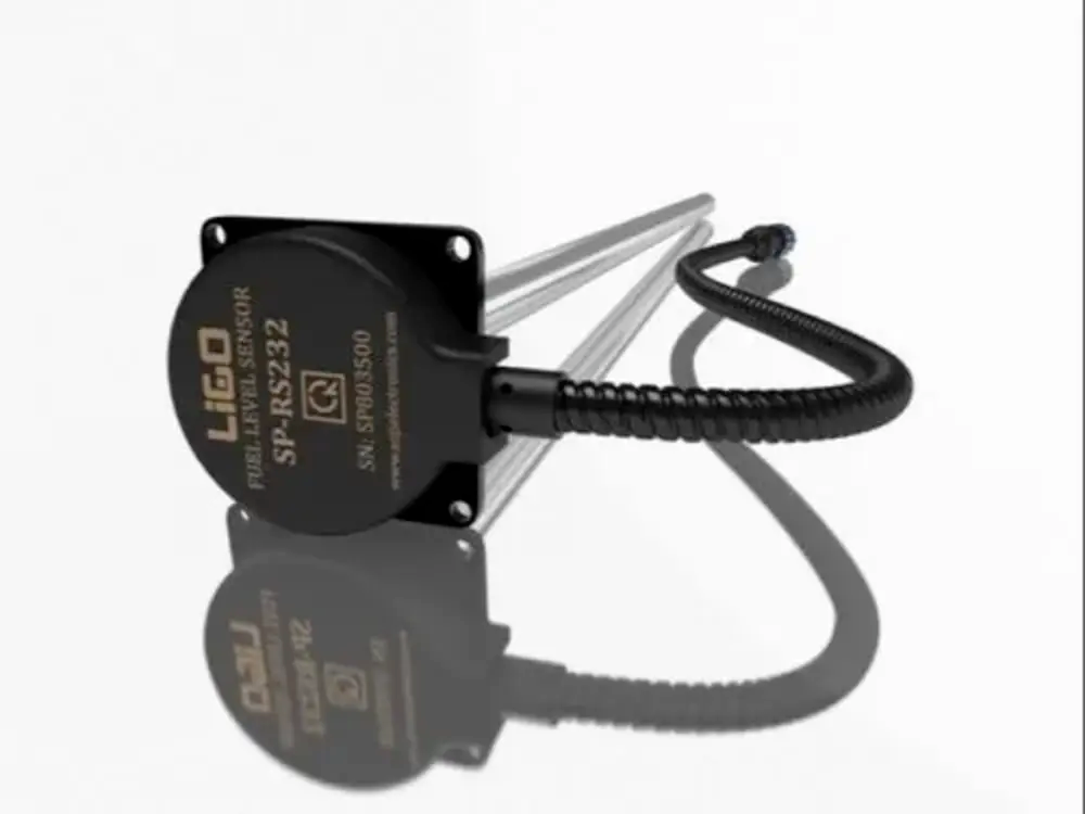 | Level Sensor Ligo fuel sensor for monitoring Diesel and Petrol level in vehicle fuel tanks and DG sets. View product → |
Frequently asked questions
How do you choose the right tank level sensor replacement?
Start with the measurement job, then match the sensor to the liquid, tank conditions, mechanical connection, output, and control-system input.
Can a point-level switch replace a continuous level transmitter?
No. A point-level switch provides an on or off signal, while a transmitter supplies a live level value for monitoring or volume calculation.
What should you check before installing a replacement level sensor?
Check the process connection, mounting position, probe or float length, tank pressure and temperature, enclosure rating, output signal, and wiring.
How do you prevent control problems after replacing a tank level sensor?
Document the old sensor’s scaling, alarm limits, fail-state behaviour, and control logic, then verify each value during commissioning.
Related products
 | Level Switch Filpro offers most reliable, cost effective Side Mounted Level Switch for point level sensing. View product → |
 | Level Transmitter Float Level Transmitters Are Ideal For Continuous Level Monitoring In Water, Diesel, Chemical And Oils For Accurate Level Measurement. View product → |
 | Level Transmitter Hydrostatic liquid level transducers and transmitters with flush diaphragm is designed fora wide variety of level measurement applications. View product → |
 | Level Transmitter Ultrasonic Level Sensor is a non-contact ultrasonic continuous level measurement product based on sound technology. View product → |