The wrong sensor choice often begins with a tank dimension treated as a complete specification. By the end, you will be able to calculate the usable measuring range, identify echo risks, test temperature and hazardous-area constraints, and decide when another level technology is the better fit.
Key takeaways
- Calculate usable level range from the transducer face to minimum and maximum levels.
- Keep the beam clear of agitators, ladders, inlets and tank-wall obstructions.
- Check temperature, vapour, pressure and hazardous-area requirements before selecting the sensor.
- Define signal outputs, fault behaviour and commissioning checks before ordering.
Start with the level range, not the catalogue range
Ultrasonic level sensor selection starts with the usable level range, not the range printed in a catalogue. Measure the tank reference point, nozzle length, maximum and minimum liquid levels, and the offset between the transducer face and your process datum.
The liquid must remain below the upper blanking distance and above the minimum specified echo range.
1. Record the sensor-to-bottom distance and calculate the distance to both operating limits. Confirm that the maximum level stays outside the manufacturer’s blocking distance, or dead zone, and that the minimum level remains within the sensor’s usable measuring range.
2. Define the required accuracy, resolution, response time, and output: for example, 4–20 mA, relay, HART, Modbus, or another interface. A long response time can hide rapid filling or overfill, while excessive resolution adds no value to a tank whose surface moves several millimetres.
3. Describe the tank geometry. Note a dished or conical bottom, narrow vessel, internal coils, ladders, agitators, inlet pipes, roof beams, and nozzle walls; these can create multiple reflections or block the acoustic beam.
4. Describe the gas space and surface. Foam, floating solids, scum, severe aeration, splashing, turbulence, vapour, dust, and condensation can weaken the echo or make the sensor measure the surface layer instead of the bulk liquid. Conductivity is not required.
5. Enter the headspace temperature range. Sound velocity in air changes by about 0.6 m/s per °C, so poor temperature compensation produces level error as the gas space warms or cools. Compare frequency only after considering attenuation from vapour, dust, foam, and condensation; higher frequency narrows the beam but loses energy faster.
For hazardous locations, match the sensor, cable entries, glands, barriers or isolators, and installation method to the area classification and certification. IEC 60079 approval is a separate question from ordinary EMC or ingress protection ratings.
Check whether the tank can produce a clean echo
Ultrasonic level sensor selection starts with whether the acoustic path is clear. Mount the sensor above a surface it can see directly, not over an inlet, outlet, ladder, coil, agitator, roof beam or internal pipe.
A narrow vessel can create multiple reflections from its walls, while a dished or conical bottom can return a weak, angled echo.
Check the installation against these points:
- Measure from the transducer face to the intended process datum, including nozzle length and any mounting offset.
- Keep the highest liquid surface below the manufacturer’s blocking distance or blanking zone; an echo inside this zone cannot be processed reliably.
- Confirm the lowest required surface remains within the sensor’s minimum echo range.
- Choose a position away from falling liquid, spray, agitator blades and areas where turbulence reaches the surface.
- Check whether internal fittings sit inside the acoustic beam; a false echo can make the sensor report a stable but incorrect level.
- Leave space for the transducer’s beam angle, especially in narrow tanks where sound can strike the wall before reaching the liquid.
Surface condition determines whether the returning echo represents the liquid. Foam, floating solids, scum, severe aeration, splashing and an uneven surface can reflect or scatter the pulse, causing intermittent loss of echo or a reading from the foam layer. Vapour, dust and condensation on the transducer weaken the signal further.
Account for filling, agitation and cleaning cycles, not just a calm, clean tank. Temperature compensation matters too: air sound speed changes by about 0.6 m/s per °C.
Match the sensor to temperature, vapour, pressure and area classification
Gas-space conditions and the site’s area classification can make an ultrasonic level sensor unsuitable even when its nominal range fits the tank. It calculates distance from echo time-of-flight and an assumed sound velocity in the gas above the liquid.
Reject or escalate a model when any of these checks fails:
- Its specified gas-temperature range excludes the actual headspace temperature.
- It uses fixed or poorly compensated sound velocity; in air near ambient conditions, velocity changes about 0.6 m/s per °C. A 20°C shift changes velocity by about 12 m/s and can create a significant level error.
- Its temperature compensation relies on transmitter ambient temperature while the gas space is hotter, colder or stratified.
- Solvent vapour changes the gas composition beyond the manufacturer’s specified conditions.
- Steam or condensation interferes with the stated operating limits.
- Pressure changes exceed the specified gas-space pressure.
- The sensor’s hazardous-location certificate does not match the classified area.
- Cable entries, glands, barriers or isolators lack matching approval.
- The proposed installation method falls outside the certificate.
Temperature compensation corrects the predictable effect of gas temperature; it does not remove errors from changing gas composition, pressure or stratification. IEC 60079-related approval is not interchangeable with ordinary industrial EMC or ingress-protection ratings. During ultrasonic level sensor selection, treat an unverified gas space or certification chain as a disqualifier, not a minor accuracy concern.
Compare ultrasonic measurement with the alternatives
During ultrasonic level sensor selection, choose another technology when the surface, gas space or control objective defeats a reliable time-of-flight echo. Ultrasonic suits non-contact measurement of clean, calm liquids, but it is not the default for every tank.
| Option | When it is better than ultrasonic | Main trade-off |
|---|---|---|
| Radar | Steam, changing vapour composition, pressure variation, or a long range makes sound velocity unreliable; foam can still weaken the radar return. | Higher cost and more demanding antenna selection; buildup can attenuate the signal. |
| Hydrostatic | Foam, floating solids and turbulent surfaces obscure the level, while liquid density is stable enough to convert pressure into height. | The diaphragm is wetted and can foul, corrode or plug; density changes create level error. |
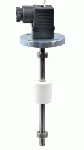
| Float | You need a simple local indication or a basic continuous signal in a clean tank with little mechanical disturbance. | A sticking float gives a false level, and guides, hinges and moving parts require inspection. |
| Capacitance | The process material has a stable dielectric constant and a probe can be installed through the vessel. | Coating on the probe changes capacitance and can imitate a rising level; calibration is material-specific. |
| Point-level switching | You need an overfill, high-level, low-level or dry-run trip rather than a continuous measurement. | It reports a switching point, not the actual level between that point and the next. |
Use radar when gas-space conditions change faster than the instrument can compensate. Use hydrostatic measurement when the liquid surface is unreadable, and use point switching when an alarm is the only decision required. Compare the required output, maintenance access and failure consequence before choosing.
Verify the signal, failure behaviour and commissioning plan
Verify the output, control-system interface and commissioning plan before accepting the ultrasonic level sensor. A correct measurement is still unusable if the loop cannot power the transmitter, the PLC interprets a fault as a valid level, or filtering delays an overfill response.
- Confirm two-wire loop power at the required load, including cable resistance, isolators and the control-system input.
- Record the configured 4–20 mA values for minimum level, maximum level, lost echo and sensor fault; verify whether failure drives the output high or low.
- Confirm HART or another communication protocol, device-description support, tag writing and diagnostic access in the host system.
- Check relay contact rating against the connected voltage, current and load type.
- Decide whether the control system needs an independent high-high overfill switch; do not treat the continuous transmitter as that protective layer without approval.
| Signal path | Acceptance check | Failure if missed |
|---|---|---|
| 4–20 mA | PLC scaling matches the sensor range and fail-safe direction | A fault appears as an ordinary level |
| HART | Host communicates and reads diagnostics | Configuration remains inaccessible |
| Relay | Contact rating and alarm logic are tested | The alarm fails under load |
| Separate high-high switch | Trip point and reset procedure are documented | Filtering delays overfill protection |
During commissioning, compare the displayed level with a measured reference at low, normal and high points. With an agitator running, test echo tracking, damping and averaging at the fastest expected fluctuation; excessive filtering creates control-loop lag.
Filpro Sensors Pvt Ltd can be asked for the exact fault codes, load limits and commissioning parameters for the selected model. Accept the installation only after a simulated lost-echo test reaches the intended alarm or shutdown state.
Related product
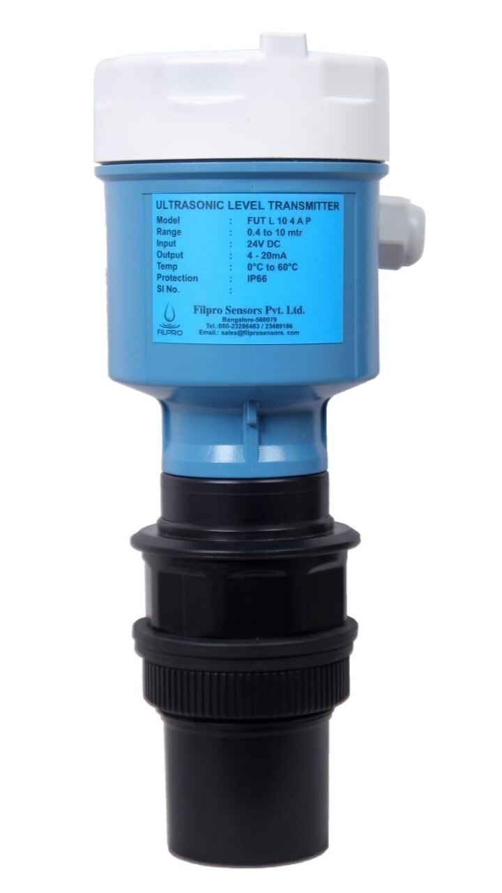
 | Level Transmitter Ultrasonic Level Sensor is a non-contact ultrasonic continuous level measurement product based on sound technology. View product → |
Frequently asked questions
Why should you start with the level range instead of the catalogue range?
Measure the transducer reference point, nozzle length, minimum and maximum liquid levels, and process datum offset. The usable range must fit these distances, including the sensor’s dead zone.
What prevents an ultrasonic level sensor from producing a clean echo?
Agitators, ladders, coils, internal supports, foam, dust, vapour, turbulence and filling streams can scatter or absorb the acoustic signal. Check the beam path and provide a calm measurement area.
Which process conditions must you check before choosing an ultrasonic sensor?
Confirm liquid and ambient temperature, vapour composition, pressure, condensation, dust, corrosion risk and the required hazardous-area classification. Select a sensor rated for each condition.
What should you compare ultrasonic measurement with?
Compare ultrasonic sensing with radar, hydrostatic, guided-wave radar, capacitance and float-based measurement. Consider foam, vapour, density changes, installation access, accuracy, maintenance and cost.
What must the commissioning plan verify?
Verify mounting alignment, empty and full levels, tank geometry, echo quality, damping, output scaling, alarm limits, loss-of-echo behaviour and integration with the control system.