A reliable calibration starts before anyone turns an adjustment screw: identify the measurement technology, make the tank and work area safe, and establish a reference level with known uncertainty. By the end, you will have a repeatable method for recording as-found error, checking the instrument across its range, making controlled adjustments, and documenting the as-left result.
Key takeaways
- Confirm the instrument range, zero datum, tank safety controls, and reference standard first.
- Record as-found readings before adjusting the level indicator.
- Test 0%, 25%, 50%, 75%, and 100% of the measurement range.
- Verify the display, output signal, alarms, and volume calculation separately.
Identify the instrument, establish the datum, and make the tank safe
Before beginning a level indicator calibration procedure, define the instrument, the reference datum, the expected measurement range, and the conditions that make the tank safe to access.
1. Identify the measurement technology and its input. Hydrostatic differential-pressure, radar, ultrasonic, guided-wave radar, displacer, float, magnetic, and sight-glass indicators require different calibration methods. Record the model, tag number, output type, configuration, alarm state, and whether you will apply a physical level input or change reference points and settings.
2. Establish the as-found condition before adjusting zero, span, damping, linearization, or sensor trim. Record the indicated level, output current or digital value, reference level, liquid temperature and density, and process conditions. An adjustment without these records cannot show whether the instrument was actually out of tolerance.
3. Define what zero means: tank bottom, outlet centreline, float’s lowest travel, lower tap, or another specified elevation. Survey the lower and upper reference elevations. For differential pressure, record sensor elevation, dry-leg or wet-leg arrangement, remote seals, assumed density, reference temperature, and any zero suppression or elevation.
4. Verify the volume table, units, and revision for tanks with volume display. Cones, dished ends, bottoms, and horizontal cylinders make level-to-volume conversion nonlinear; checking only 0% and 100% will miss an incorrect intermediate table.
5. Make the tank safe: isolate connected lines, apply lockout/tagout, depressurize, drain or empty it, control vapour and ignition hazards, and obtain confined-space authorization before entry. Document foam, vapour, condensation, turbulence, agitators, obstructions, and temperature gradients before testing ultrasonic equipment.
Take as-found readings against a traceable reference
Tank level indicator calibration starts with an as-found comparison, before changing zero, span, damping, linearization, offset, or sensor trim. Create the reference from a calibrated dip tape, certified sight glass, surveyed elevation, volumetric fill, weigh-scale result, or calibrated reference transmitter. Record its certificate number, traceability, measurement uncertainty, reference temperature, and the exact datum used.
1. Identify the measurement technology and choose a matching reference method. For radar and guided-wave radar, compare measured distance and configured tank reference point; verify tank height, probe length, nozzle or flange reference, blocking distance, false-echo map, and dielectric setting. Do not hide an installation error with a display offset.
2. For hydrostatic differential pressure, record liquid density, temperature, sensor elevation, and dry-leg, wet-leg, or remote-seal arrangement. Use ΔP = ρgh to convert the reference level to expected pressure; incorrect density can produce the wrong level even when the pressure calibration is accurate.
3. Take readings at the lowest, mid-scale, and upper reference points without adjustment. At each point, record reference level, displayed level, 4–20 mA output or digital value, process conditions, configuration, and alarm state.
4. Calculate error at every point: indicated value minus reference value. Preserve the signed result, units, and percentage of span, then compare it with the instrument tolerance before making any adjustment.
For float, displacer, magnetic, and sight-glass devices, inspect sticking, restricted travel, alignment, blocked connections, scale position, and float condition first. A moving indication proves operation, not accuracy.
Apply five test points and adjust the correct measurement technology
Apply five test points—0%, 25%, 50%, 75% and 100% of the defined span—to complete a level indicator calibration procedure. For tank level indicator calibration, establish each point with the traceable reference, allow the reading to settle, and adjust only after comparing the indication with the reference.
- 0%: Set the lower span elevation.
- 25%: Confirm low-range linearity.
- 50%: Check the midpoint.
- 75%: Confirm upper-range linearity.
- 100%: Set the upper span elevation.
| Technology | Correct test and adjustment |
|---|---|
| Hydrostatic differential-pressure | Apply equivalent ΔP using ΔP = ρgh. Enter density, reference temperature, sensor elevation, and dry-leg, wet-leg or remote-seal details; wrong density produces wrong level. |
| Radar or guided-wave radar | Compare measured distance with the reference. Check tank height, probe length, nozzle reference, blocking distance, false-echo map and dielectric setting before changing offset. |
| Ultrasonic | Test with representative vapour, foam, turbulence and temperature conditions. Correct sound-path settings, not just tank dimensions. |
| Mechanical indicator | Move the mechanism through five equivalent positions and correct linkage zero, span and friction. |
| Float indicator | Raise and lower the float through each point. Verify orientation, density rating, travel and freedom from sticking. |
| Magnetic indicator | Compare the follower or flags with the controlled level and scale datum. Do not adjust a 4–20 mA signal unless a separate transmitter exists. |
| Sight glass | Compare the visible liquid line with the reference level and scale. Clear blocked connections and correct scale alignment, not the glass itself. |
Verify the signal, display, alarms and volume calculation separately
Separate tank level indicator calibration from the checks that follow it: a correct sensor can feed a wrong display, and a correct display can use wrong volume data.
| Check | What it proves | Record |
|---|---|---|
| Instrument accuracy | The measured physical level agrees with the traceable reference at each test point. | Reference level, indicated level, process condition, configuration and as-found result |
| Loop performance | The signal reaches the control system correctly. | Lower-range value, upper-range value, output current or digital value, loop supply and polarity |
| Display scaling | The receiving indicator, PLC or DCS converts the signal into the intended level units. | Injected signal, displayed value, engineering-unit range and configured offset |
| Alarm operation | Each alarm activates and clears at the intended condition. | Setpoint, deadband, delay, alarm state and annunciation |
| Volume calculation | The level-to-volume conversion matches the tank geometry. | Displayed volume at intermediate levels, units, strapping or linearization table revision |
A 0% level does not always mean 4 mA, and 100% does not always mean 20 mA. Verify the configured range when elevated zero, suppression or a shifted engineering range is used; checking only the endpoints will miss a wrong intermediate volume table.
For ultrasonic instruments, test with representative vapour, foam, condensation and turbulence. For radar or guided-wave radar, verify the tank reference, probe or nozzle dimensions, blocking distance and false-echo settings; changing an offset can conceal an installation error.
Return the indicator to service and complete an auditable record
Return the indicator to service only after the as-left results meet the specified tolerance at every test point and the process connection, covers, valves, wiring, and display are restored to their operating condition.
For ultrasonic instruments, record whether vapour, foam, condensation, turbulence, agitator movement, obstructions, and temperature gradients matched service conditions; an empty-tank result does not prove performance in a foaming tank.
The tank level indicator calibration record should contain:
- Instrument tag, serial number, range, units, date, technician, and next-due basis.
- Reference method, reference-equipment identification, calibration due date, and traceability evidence.
- As-found and as-left values, including reference level, indicated level, output current or digital value, configuration, process conditions, and alarm state.
- Adjustments made to zero, span, damping, linearization, sensor trim, or other settings.
- For a 4–20 mA loop, lower-range value, upper-range value, each output, loop supply, polarity, and receiving-indicator scaling. Record any elevated zero, suppression, or shifted range.
- For differential-pressure instruments, assumed density and temperature, sensor elevation, and dry-leg, wet-leg, or remote-seal arrangement.
- For volume indication, the tank geometry or strapping-table identification, units, and revision; verify an intermediate point, not only 0% and 100%.
Document alarm, trip, interlock, and independent overfill-protection tests separately. For equipment from Filpro Sensors Pvt Ltd, retain the model-specific configuration and display orientation so a correct reading is not accepted from the wrong setup. Have an authorised reviewer sign the completed level indicator calibration procedure before release.
Related products
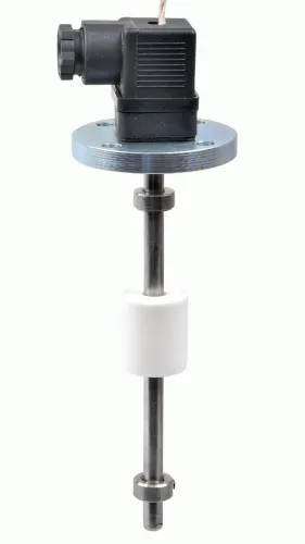
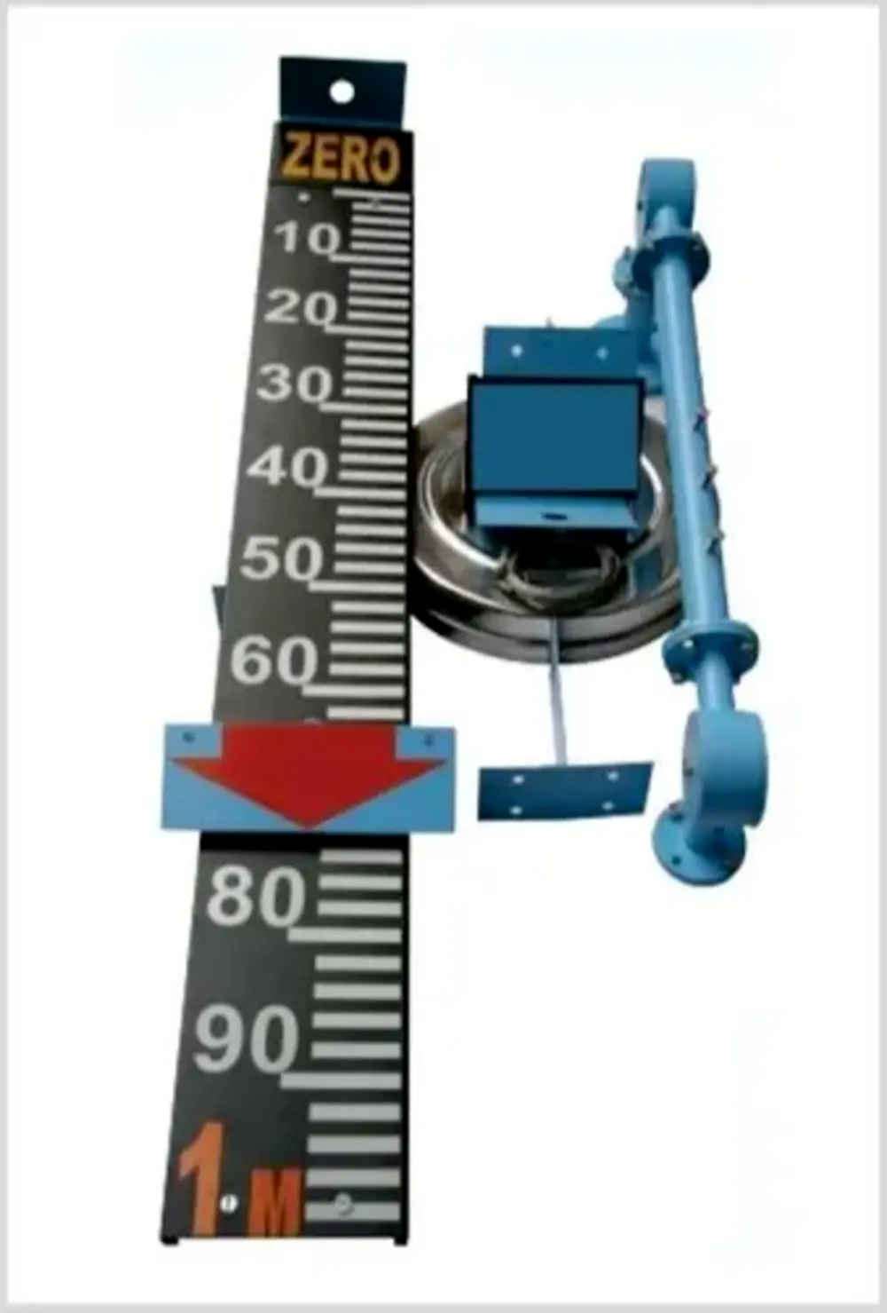 | Level Indicator The Float & Board Level Indicators consists of a float connected to a pointerthrough a rope via a set of pulleys. View product → |
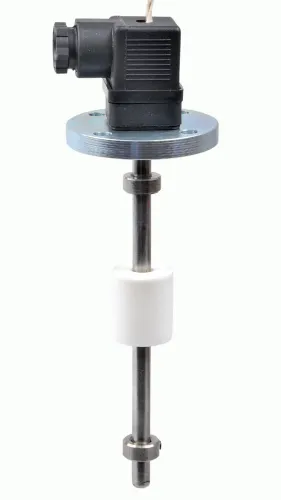
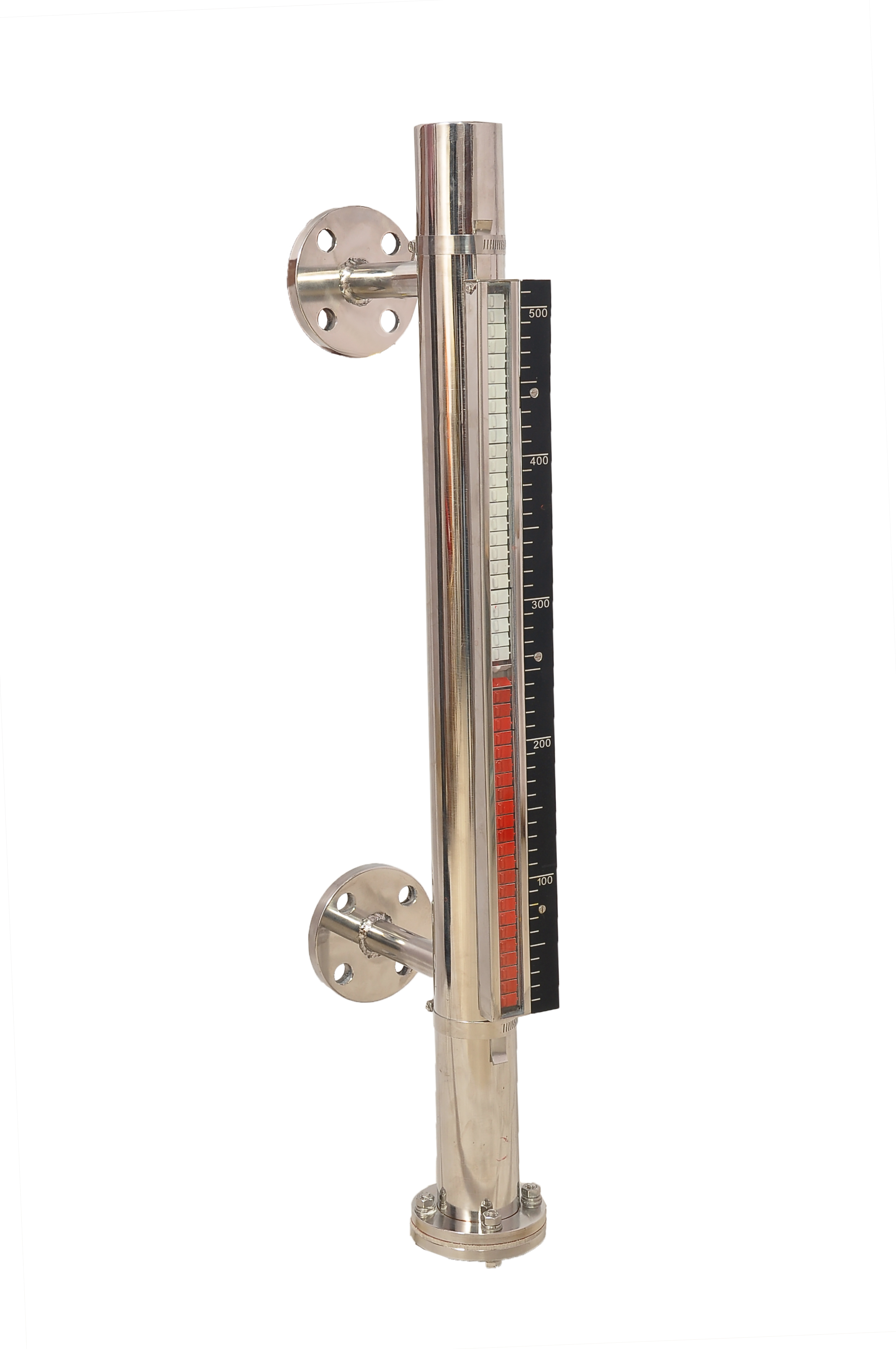 | Level Gauge FILPRO offers Magnetic Level Indicator provides clear, high clarity indication of liquid level. View product → |
Frequently asked questions
What must you confirm before starting tank level indicator calibration?
Identify the instrument, measurement range, reference datum, access conditions, isolation requirements, and tank hazards before testing.
How do you take as-found readings during calibration?
Compare the indicator with a traceable reference at the existing level and record readings before making adjustments.
Which test points should a level indicator calibration use?
Apply five points across the range: 0%, 25%, 50%, 75%, and 100%, using the points required by the instrument procedure.
What must you verify after adjusting the level indicator?
Check the local display, transmitted signal, alarm setpoints, and volume calculation separately before returning the instrument to service.
Related products
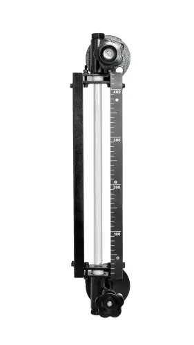
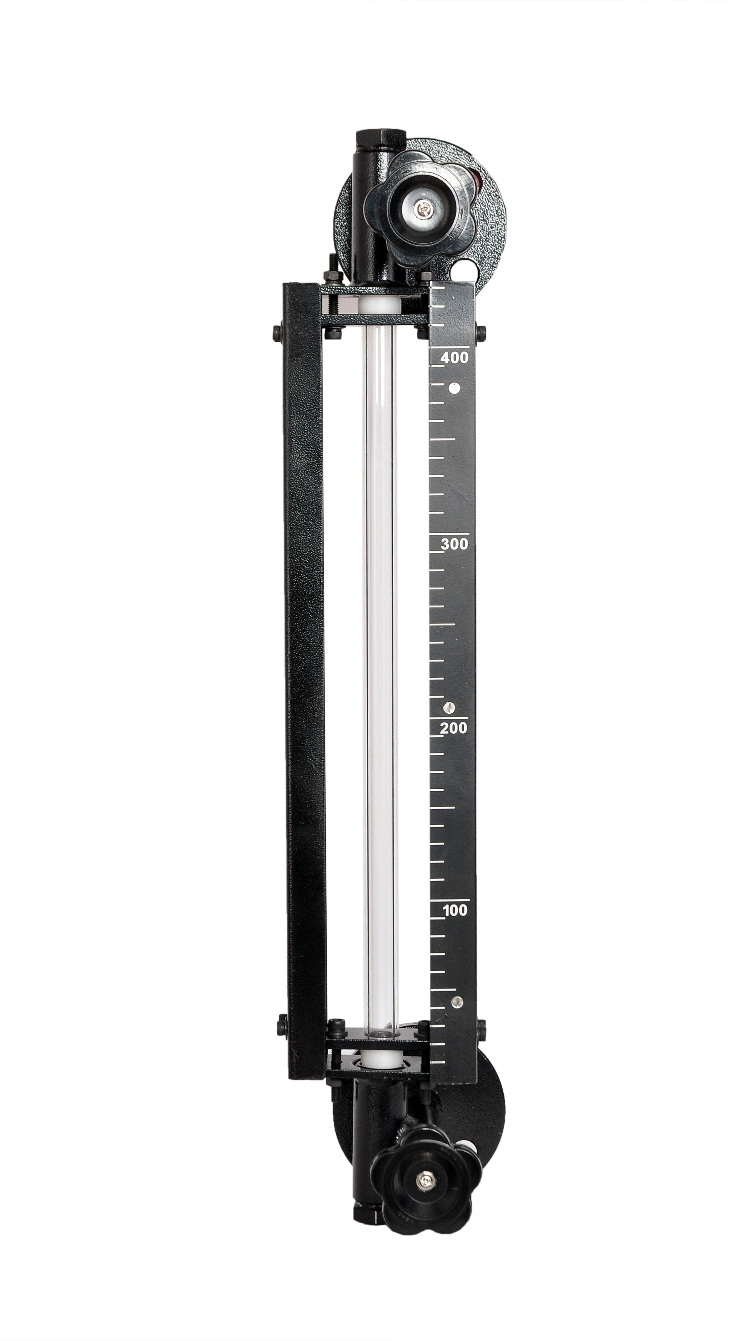
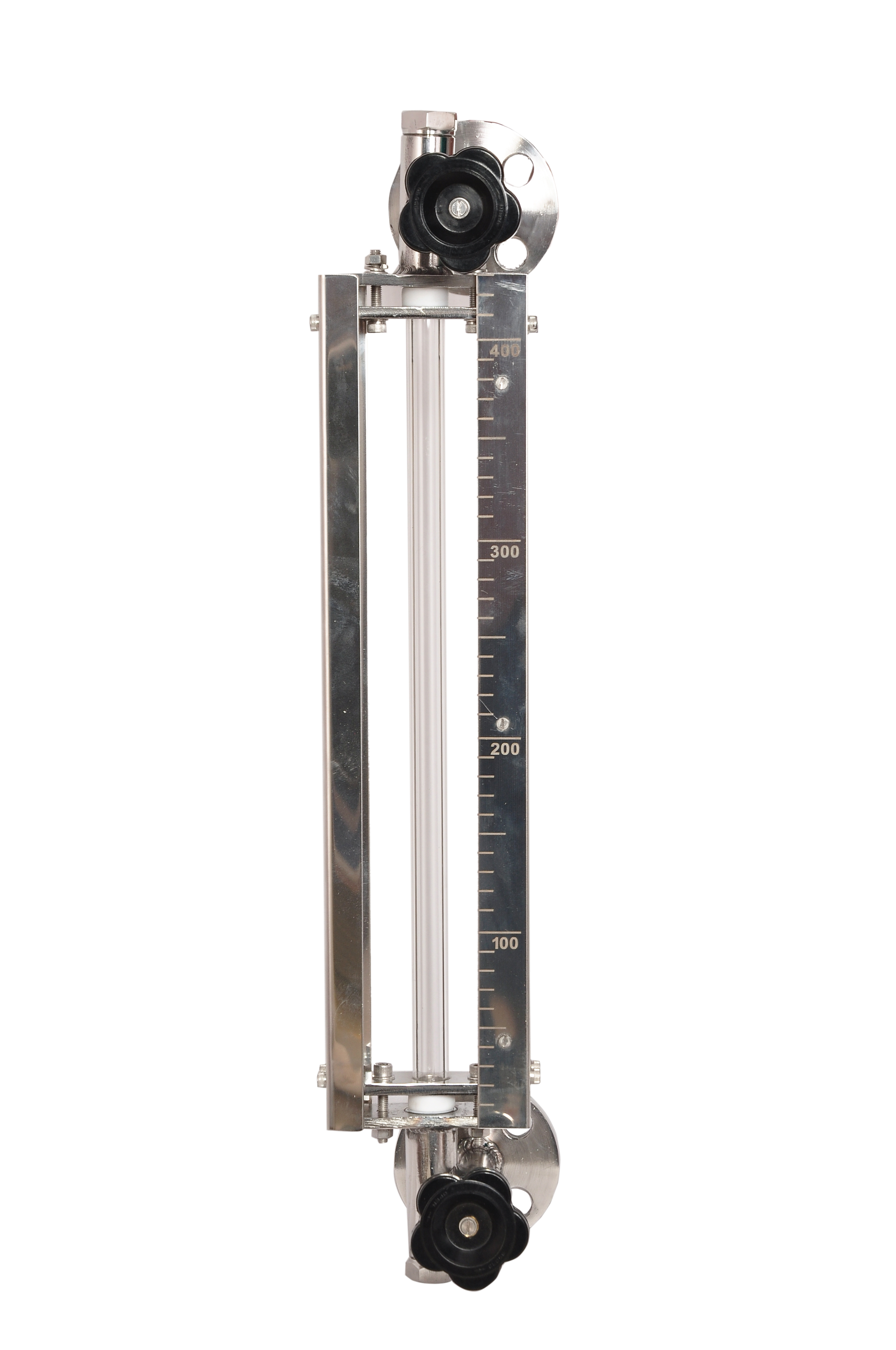 | Level Gauge Tubular Glass Level Indicator is used for visual level indication of liquid in storage and process tanks. View product → |
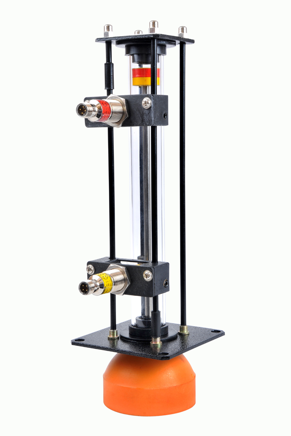 | Level Gauge Oil Level Indicator is designed to indicate the coolant and hydraulic oil level inside the tank with a visual indicator above the tank. View product → |