Repeated pump starts usually come from a false level change, too little separation between start and stop points, a hydraulic problem, or a failed run signal. By tracing the level, command, feedback and flow in order, you can identify whether the controller, sensor, pump or process is causing the cycling and choose a remedy that protects the motor.
Key takeaways
- Trend level, pump command, feedback, pressure, flow, and valve states together.
- Test the float, transmitter, and controller wiring as separate parts of the loop.
- Increase the start-stop differential only after confirming the level signal is stable.
- Check minimum pump run time, pipework, valves, and tank capacity for hydraulic causes.
Confirm that the cycling is real and identify its pattern
Confirm the pump is truly cycling before changing the level controller. Treat repeated starts within minutes, or starts before the tank reaches a meaningful level difference, as rapid cycling. For level controller troubleshooting pump cycling, trend the liquid level, pump command, pump-running feedback, discharge pressure or flow, and valve states on one time axis.
- Compare the start and stop levels. If the pump starts at the same level but the measured level remains steady, inspect a siphon, leaking discharge isolation valve, or interaction between parallel pumps.
- Check whether the level rises after shutdown because liquid drains back through a leaking check valve. Observe the discharge line with the pump off and compare its drain-back rate with the tank’s level rise.
- Separate the start command from run feedback, fault status, permissive, and restart timer. A failed auxiliary contact, wrong VFD-running bit, overload trip, lost permissive, or PLC I/O fault can make the controller issue the same start repeatedly.
- Compare pump capacity with inflow. If the pump removes more liquid than the process supplies, a small tank will cross the stop level almost immediately after every start; that is a process-capacity problem.
When commands and run feedback agree, a narrow start-stop separation is the likely trigger. Increase the deadband to prevent immediate restarting, but allow for a larger level swing and more storage volume. Variable-speed drives still cycle when sleep and wake thresholds, minimum speed, ramps, or minimum-flow requirements are poorly coordinated.
Test the float, transmitter and controller wiring separately
Separate the three stages before changing settings: prove the float or transmitter changes state, prove the wiring carries that state, then prove the controller reacts at the correct threshold. Lock out the pump output during these tests so a false command cannot start the pump.
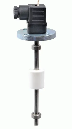
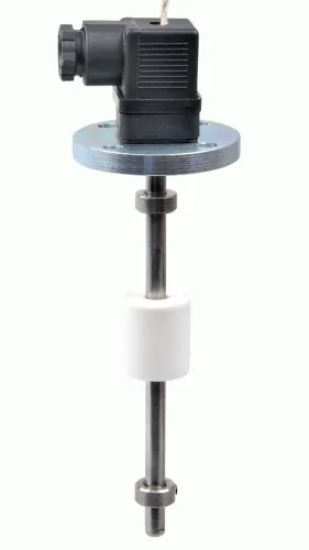
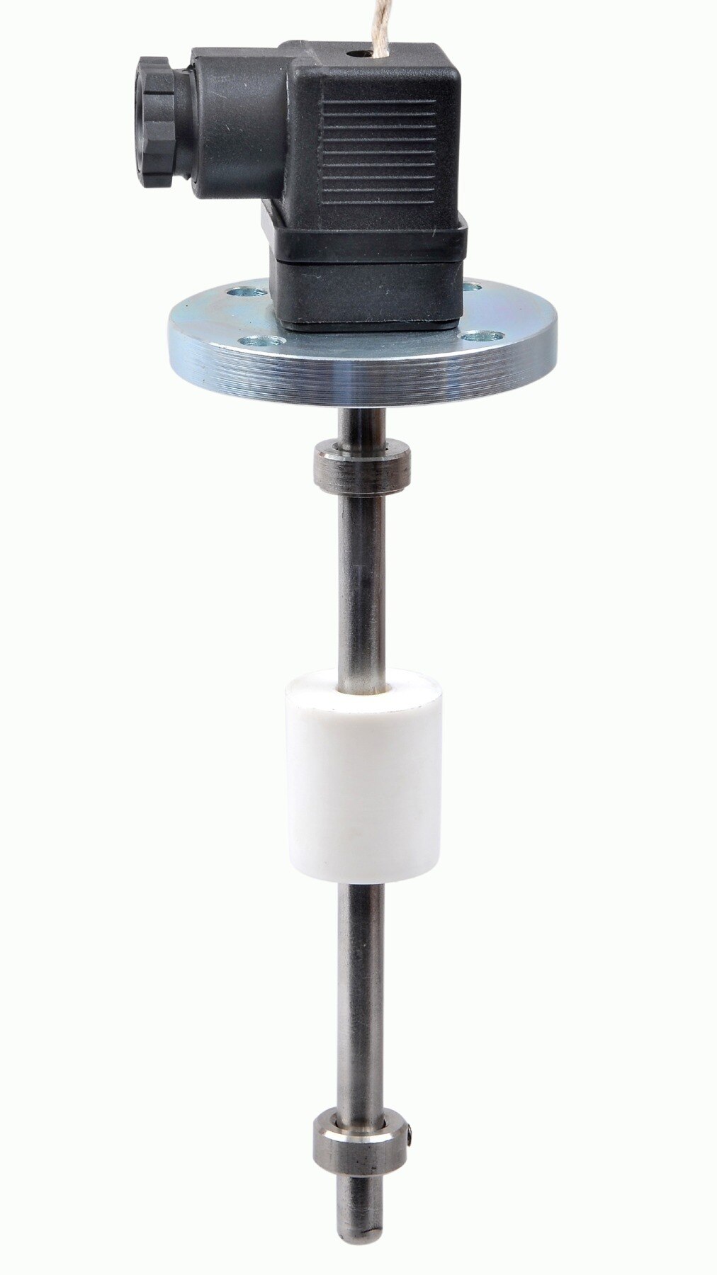
1. Float switch: disconnect its wires at the controller terminals and check continuity with a multimeter while moving the float through its full travel. The contact must change state at the intended high or low position and remain steady; flex the cable or stem during the test to expose intermittent contacts.
A float that sticks against a wall, guide, pipe or foam layer has failed this test.
2. Transmitter: record its output at a steady low level, then at a steady high level. A 4–20 mA transmitter should change smoothly and hold its signal; a sudden jump or drifting value points to the sensor, supply, or signal cable rather than the controller.
3. Wiring and controller: check terminal tightness, polarity, shield termination and the selected NO or NC input. Open and close the input, or inject the specified simulated signal, while watching the controller indication and pump command. The command should change once at the configured threshold, not chatter.
For level controller troubleshooting, trend sensor state or mA, controller command, pump-running feedback and level on one time axis. If the sensor signal is stable but the command changes, investigate controller logic or wiring; if the command is stable but the pump stops and restarts, investigate the contactor, feedback circuit or power supply.
This separation prevents pump cycling from being blamed on a sensor that never changed state.
Increase the level differential and coordinate the control logic
Set the pump-start level high and the pump-stop level low enough to create a meaningful deadband.
A wider start-stop separation prevents the level controller from restarting the pump immediately after the level crosses the stop point, but it also creates a larger operating swing and requires enough tank volume to hold that swing without a high-level trip.
Choose the settings as a coordinated group:
- Start and stop levels: Confirm the tank can accommodate the full band, the pump remains submerged at the stop level, and the incoming flow will not reach the start level too quickly.
- Minimum off-time: Hold the pump off after a normal stop long enough to prevent rapid successive starts. Set this against the motor starter or VFD limit, while keeping it short enough to avoid overflow.
- Minimum run time: Keep the pump running long enough to remove a meaningful volume. A tank that supplies less liquid than the pump removes will cross the stop level almost at once, so a longer delay cannot fix that capacity mismatch.
- Start feedback: Require a valid running signal after the start command. Treat missing feedback, an overload, or a lost permissive as a failed start, not as permission to issue repeated starts.
For a VFD, coordinate the sleep and wake thresholds, minimum speed, acceleration and deceleration ramps, and restart delay. If the drive cannot operate steadily above its minimum speed, the pump may stop and wake repeatedly even with a wide level band.
Check the pump, pipework and tank capacity for a hydraulic cause
Hydraulic faults can make every restart legitimate, even when the level controller works correctly. A pump that removes liquid faster than the process replaces it can cross the stop level seconds after starting, especially in a small tank. That is a tank-capacity and process-flow problem, not a controller fault.
| Fault | What happens | Check |
|---|---|---|
| Tank too small or pump oversized | The level crosses the stop point immediately after each start | Compare pump capacity with the measured inflow and usable tank volume |
| Leaking check valve | Liquid returns through the stopped pump, raising the tank level for another start | Watch whether the discharge line drains back after shutdown |
| Siphon or leaking discharge isolation valve | Liquid continues moving with the pump off, changing the level or pressure unexpectedly | Isolate the discharge and compare level and pressure behaviour |
| Blocked inlet or undersized suction pipe | Restricted inflow causes unstable pump operation and rapid emptying near the pump intake | Check inlet screens, suction pressure, pipe diameter and blockage |
| Parallel pumps interacting | One pump changes the flow or pressure seen by another, producing repeated starts | Run each pump separately, then compare flow, pressure and valve states together |
For level controller troubleshooting pump cycling, trend tank level, pump command, running feedback, discharge pressure or flow, and valve states on one time axis. A stable indicated level with repeated commands points toward siphoning, valve leakage or pump interaction; a level that rises after shutdown points strongly to backflow.
Compare the level-rise or level-decay rate with the discharge isolation arrangement before changing controller settings.
Repair the cause, then validate the installation under real conditions
Repair the root cause, record every change, and retest the installation under its normal operating conditions before declaring the pump cycling problem solved. A longer anti-restart delay protects the motor from rapid starts; it does not correct a false stop signal, narrow operating band, leaking valve, or undersized tank.
Set the delay within the motor starter or VFD limits, then check that it will not hold the pump off long enough to cause a high-level trip or overflow.
1. Trend liquid level, pump command, running feedback, discharge pressure or flow, and valve states on one time axis. This separates a genuine control fault from backflow, a siphon, a leaking discharge isolation valve, or interaction between parallel pumps.
2. Repair the confirmed cause, then record the fault, measured evidence, component changed, controller settings, contact logic, delay value, and date. Include the tank’s start and stop levels so another technician can reproduce the test.
3. With the pump stopped, check whether the discharge line drains back and compare the level-rise rate with the discharge isolation arrangement. A leaking check valve can create a legitimate restart that looks like controller cycling.
4. Run several complete fill-and-pump-down cycles with normal inflow, discharge conditions, valve positions, and parallel-pump sequencing. Do not use a PID loop as the first fix for a discrete start/stop output; use explicit hysteresis unless a tuned VFD system is being installed.
For replacement selection, Filpro Sensors Pvt Ltd can help match the switching device and controller to the tank’s turbulence, mounting position, contact logic, and required operating band. Accept the repair only when the pump stops and restarts at the documented levels without premature starts, nuisance trips, or overflow risk.
Related products
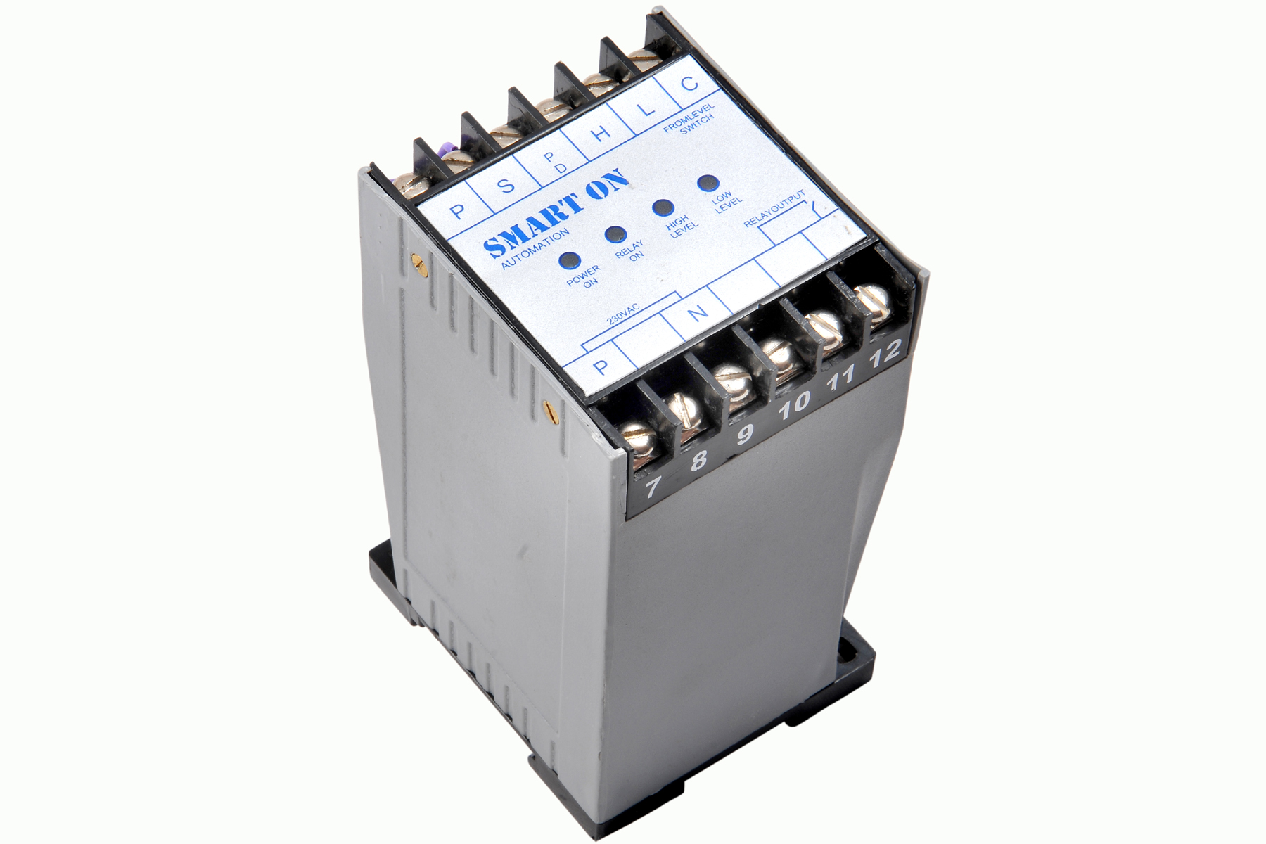 | Controller Filpro Sensors Pvt Ltd manufactures industrial Level Controller (Smart On) to automatically start & stop the pump. View product → |
 | Level Switch Filpro offers most reliable, cost effective Side Mounted Level Switch for point level sensing. View product → |
Frequently asked questions
How do I confirm that a pump is truly cycling?
Trend the liquid level, pump command, pump-running feedback, discharge pressure or flow, and valve states on one time axis. Repeated starts within minutes or before a meaningful level difference indicate rapid cycling.
How should I test the float, transmitter, and controller wiring?
Test each part separately. Check float movement and contacts, compare transmitter output with actual level, and verify wiring continuity, polarity, shielding, terminals, and controller input readings.
How can I stop a level controller from cycling the pump?
Increase the start-stop level differential after confirming the signal is stable, then coordinate start, stop, minimum-run, minimum-rest, and alarm logic so conflicting commands cannot restart the pump.
What hydraulic problems cause pump cycling?
Inspect pump capacity, restricted or oversized pipework, leaking or rapidly closing valves, check-valve operation, discharge pressure, flow, and tank working volume. A small tank or excessive pump flow can empty the control band quickly.
Related products
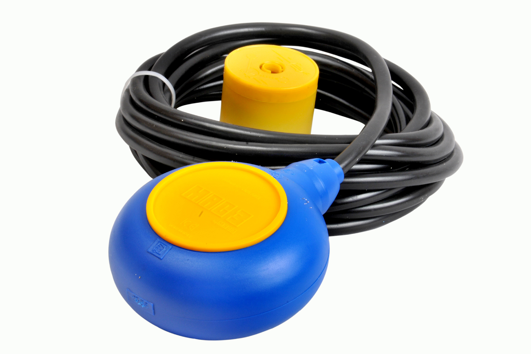 | Level Switch Cable Float Switch is mainly used for the automatic working of small pumps and cellar emptying pumps in liquids a little bit agitated. View product → |
 | Level Switch Plastic Miniature Level Switch is available in PP construction with PP Float Switching Voltage: 24V DC Switching current: 0.1A Mounting thread size:... View product → |