An overfill event begins with a rising liquid level but becomes a safety problem when the sensing point, control logic and final shutdown action fail to stop the inflow. By the end, you will be able to trace that protection sequence, distinguish a warning from an independent shutdown, and check whether the setpoint, wiring, installation and tests suit the tank.
Key takeaways
- Set the trip point below the tank’s safe maximum fill level.
- Use a separate alarm or shutdown response for high-high protection.
- Test sensor, wiring, relay logic, alarm, and final shutdown device together.
- Check turbulence, foam, buildup, and mounting position before selecting the switch.
How the switch detects a high liquid level
A tank overfill protection level switch detects one defined high or high-high point. When liquid reaches its sensing element, the device changes contact state—opening or closing an electrical circuit—and sends a discrete signal to an alarm, pump shutdown, inlet-valve closure, or emergency isolation system. It does not continuously report the level between those points.
A high-level warning and an independent high-high shutdown switch can use separate setpoints and protective loops.
The sensing method determines what physically changes:
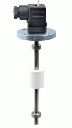
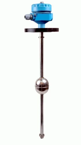
- A float or displacer rises with the liquid and actuates a mechanical switch or magnetic contact. Density must provide enough buoyancy; viscosity, wax, solids, cage blockage, poor orientation, or an obstruction can stop movement.
- A vibrating-fork switch monitors its fork’s oscillation. Liquid touching the fork changes that vibration and triggers the output. Coating, foam, entrained solids, turbulence, or unsuitable mounting can cause missed or false trips.
- A capacitance switch detects a change in electrical capacitance when product reaches the probe. Dielectric constant, conductive deposits, coating, grounding, and probe geometry affect the setpoint, so calibrate it with the actual product and installation.
| Instrument | Signal | What it tells you |
|---|---|---|
| Overfill level switch | Discrete contact or switching signal | Liquid reached one protective point |
| Hydrostatic transmitter | Changing electrical output | Calculated level from liquid pressure |
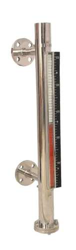
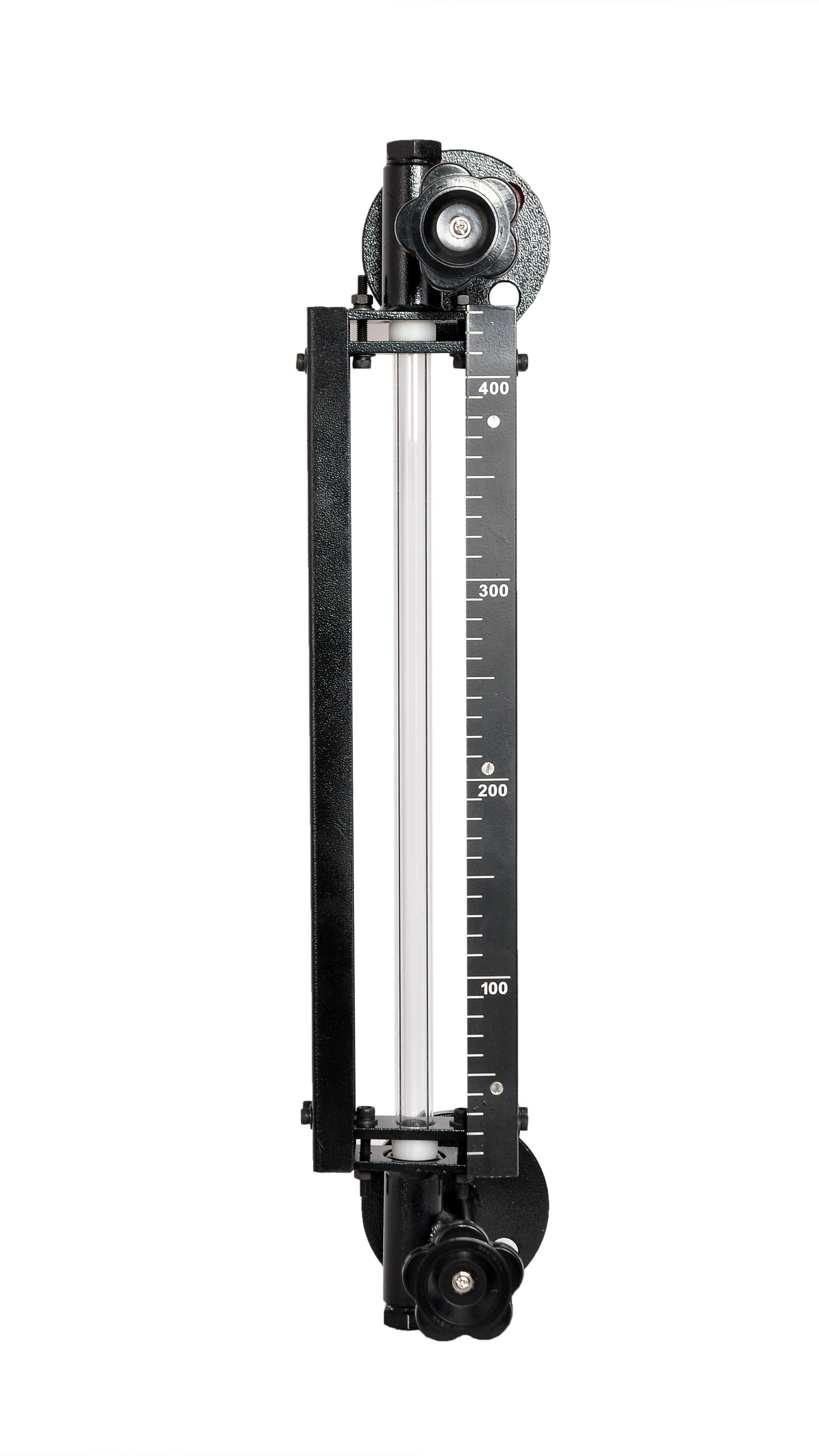
| Float-and-board indicator or other continuous instrument | Changing position or output | Rising or falling level across the tank |
A credited high-high function includes the sensor, logic solver, and final element; the switch alone cannot guarantee overfill prevention.
From rising liquid to alarm or shutdown
A tank overfill protection level switch turns rising liquid into protective action when the liquid reaches its effective sensing level. The switch changes electrical state, and an input circuit or interposing relay sends that signal to a logic solver, PLC or safety system.
The system then annunciates an alarm, stops a pump, closes an inlet valve or initiates emergency isolation through the final element.
| Function | Signal and action | Purpose |
|---|---|---|
| High-level warning switch | Sends an alarm to the operator, who can stop filling or correct the line-up | Provides time for human intervention before overfill |
| Independent high-high switch | Sends a separate trip signal to a logic solver, which shuts down the filling source or isolates the inlet | Provides automatic protection when the warning is missed or the response is too slow |
Normally open contacts close when the switch operates; normally closed contacts open. The contact choice depends on the circuit design, but a de-energise-to-trip arrangement treats loss of power, broken wiring or loss of the permissive signal as a trip condition instead of allowing filling to continue unnoticed.
The protection belongs to the complete loop: sensor, input circuit, logic solver and final element. Valve stroke time, pump rundown and liquid already moving through the pipe determine whether the loop acts before overflow, not the switch’s response time alone.
Latch the alarm or high-high trip when repeated filling must not resume unnoticed. Require a manual reset after the level is verified safe and the cause is corrected; automatic reset or restart after power restoration can restart the pump and recreate the filling hazard.
How to choose the trip level and prove the response
The high-high setpoint belongs below the maximum safe fill level by a calculated free-volume margin, not at a fixed percentage of tank height. That margin must contain liquid entering while the sensor detects level, logic processes the signal, a valve strokes or a pump runs down, and an operator responds where applicable.
Calculate inflow over the complete response time, including valve-stroke time, pump rundown, shutdown sequencing and pipeline inventory. Add allowances for liquid surge, thermal expansion, measurement uncertainty and tank-volume calculation error; assess excessive inflow as a separate scenario.
Define response time from liquid reaching the effective sensing level until the process reaches a safe state, not from the switch’s electrical response alone.
| Basis | What it misses or includes | Decision |
|---|---|---|
| Percentage of tank height | Assumes tank geometry and ignores inflow, delays, surge and expansion | Insufficient by itself |
| Volume-and-time balance | Uses actual tank geometry, inflow, pipeline inventory, final-element timing and safety margins | Set the trip from the calculated free volume |
| Installed-loop proof test | Tests the switch alone rather than the logic and final element | Does not prove overfill protection |
A tank overfill protection level switch is not proof against wrong valve line-up, blocked outlets, leaks, failed isolation, excessive inflow or trapped-liquid expansion. Analyse those cases separately and add safeguards where the trip cannot create a safe state.
Prove the complete loop by:
- Testing the switch at the relevant process condition or a realistic level simulation.
- Verifying input, logic, alarm or trip annunciation, and the shutdown sequence.
- Confirming valve movement or pump shutdown, then restoring the system.
- Controlling every bypass or inhibited trip formally.
IEC 61511 SIL applies to the complete safety instrumented function after hazard and risk assessment, not to switch technology alone.
What failures the wiring and test plan must reveal
The tank overfill protection level switch must be tested as a complete loop, not as an isolated sensor. The plan must reveal whether power loss, an open cable, a false sensor state, relay failure, a bypass, or a failed valve produces a defined fault alarm, a safe shutdown, or both.
| Arrangement | Normal condition | Failure consequence | Operator indication |
|---|---|---|---|
| Energise-to-run | Relay coil energised to permit filling | Loss of power, broken cable, failed relay, or de-energised input stops filling | Shutdown plus a distinct fault alarm; no automatic restart |
| De-energise-to-trip | Relay coil de-energised only for a trip | Loss of power or broken cable trips the process; a welded relay or bypass can defeat the trip | Trip indication and fault alarm where the cause is distinguishable |
A stuck float or fouled probe can report a permanently low level and allow overfilling, or a permanently high level and cause a nuisance shutdown.
An interposing relay gives the logic solver a suitable contact and isolation, but a shared supply, cable route, impulse connection, or heat, flooding, vibration, or chemical exposure can defeat independence from the basic level-control transmitter.
Use a proof test that exercises the installed loop:
- Apply the relevant process level or a controlled simulation.
- Verify sensor state, input status, logic action, alarm and trip indication.
- Confirm pump stopping or shutdown-valve movement, including stroke or fail time.
- Verify manual reset, safe level, and restoration without automatic restart.
- Authorise every bypass or inhibited trip, display it at the operator station, and record the reason, time, tester, result, and removal.
How installation and instrument choice affect real-world operation
A tank overfill protection level switch detects the bulk level only when its location reflects the tank’s actual liquid behaviour. Mount it away from inlet jets, vortexes, agitators, ladders and internal obstructions; keep the sensing point clear of the wall, with the orientation specified by the manufacturer.
Use a stilling or protective arrangement when turbulence, splashing, foam or vapour could wet the sensor prematurely. A poorly drained nozzle can retain liquid and create a false high-level signal, so provide drainage or choose a self-draining mounting.
- Choose a float switch only when the product provides enough buoyancy and the float can move freely. Check density, viscosity, wax or solids deposits, cage blockage and mechanical clearances.
- Choose a vibrating fork after checking coating, viscous liquid, entrained solids and turbulence. Confirm the actual product’s density and viscosity fall within the approved range; buildup can prevent a trip or cause a false one.
- Choose a capacitance probe when the dielectric constant remains stable. Provide the specified grounding and calibrate it in the actual product, not water or a laboratory substitute.
Treat enclosure ingress protection, process and ambient temperature, corrosion compatibility and hazardous-area classification as functional limits. Use compatible cable glands and the approved intrinsically safe or explosion-protected installation method.
When evaluating Filpro Sensors Pvt Ltd or another supplier, request contact logic, setpoint repeatability, process limits, a mounting drawing, approvals, fault response and the proof-test method. A catalogue model is not the complete overfill function.
Related product
 | Level Switch Filpro offers most reliable, cost effective Side Mounted Level Switch for point level sensing. View product → |
Frequently asked questions
How does a tank overfill protection level switch detect high liquid level?
It detects one defined level with a sensing element, then changes electrical contact state when liquid reaches that point.
What happens after the switch detects a high level?
Its discrete signal can trigger an alarm, stop a pump, close an inlet valve, or initiate emergency isolation through the control system.
How do you choose and prove the trip level?
Set the trip point below the tank’s safe maximum, account for filling rate and response time, then test the complete alarm or shutdown chain.
What installation conditions can cause overfill protection to fail?
Turbulence, foam, liquid buildup, poor mounting, incorrect wiring, failed relays, and untested final shutdown devices can prevent the intended response.