The correct rating comes from the highest pressure the complete transmitter assembly will face at its process connection, not from tank height alone. By the end, you will be able to calculate that pressure, distinguish continuous, transient and test limits, and specify a range that protects the instrument without sacrificing level resolution.
Key takeaways
- Separate pressure rating from calibrated measuring range.
- Calculate static head, operating pressure, temperature, and pressure spikes.
- Match gauge, absolute, or differential pressure to the measurement setup.
- Verify the rating of every wetted pressure-boundary component.
What does a level transmitter pressure rating actually mean?
A level transmitter pressure rating is the pressure its pressure boundary can withstand at the process connection. It is different from the measuring range: measuring range is the level or pressure span calibrated for the output signal, while pressure rating concerns physical containment.
A differential-pressure transmitter might measure only 5 kPa of level differential while facing several megapascals of static pressure across both ports.
| Limit | What it means | How to use it |
|---|---|---|
| Maximum working pressure | Continuous pressure limit during operation | Keep the highest sustained connection pressure below this value |
| Proof pressure or overpressure limit | Short-duration pressure the boundary survives without unacceptable damage | Treat it as a test or upset limit, not a continuous operating target |
| Burst pressure | Pressure at which the boundary can fail or rupture | Never select or operate against this figure |
For a vessel, pressure at the lower connection is approximately ρgh plus gas-space pressure above the liquid. Here, ρ is liquid density, g is gravity, and h is the maximum liquid height. A 10 m water column at roughly 1,000 kg/m³ produces 98,100 Pa, or 0.981 bar gauge.
A liquid at twice water’s density produces about 1.96 bar over the same height.
Use the maximum credible density and maximum liquid level, not normal values. Add vessel overpressure and assess credible transients such as:
- Pump starts, valve closures, water hammer, steam-out, thermal expansion of blocked-in liquid, emergency depressurisation, and pressure tests
For varying or vacuum gas-space pressure, include the reference side’s maximum and minimum pressure in the rating assessment.
How do you calculate the highest pressure at the transmitter?
Calculate the highest pressure at the transmitter connection, not just the pressure during normal operation. The hydrostatic pressure calculation starts with the vertical distance from the transmitter diaphragm or lower impulse connection to the maximum liquid level.
1. Measure the maximum liquid level from the transmitter diaphragm or lower impulse connection to the highest credible level. Use the maximum operating height, including a high-high level or credible overfill condition.
2. Use the maximum process density at the actual temperature and concentration, then calculate liquid pressure as density × gravity × height. Heated water, diesel, acids, caustic solutions and heavy oils produce different pressures at the same height.
3. Add the vessel pressure above the liquid in a closed tank. Also check pressure at the upper connection and any static pressure applied across both transmitter ports.
4. Add credible pressure sources beyond the liquid column. Check pump discharge, blocked or pressurised lines, agitation, rapid valve closure, water hammer, thermal expansion of trapped liquid, steam-out and emergency conditions.
5. Check the process temperature pressure rating for the flange, connection, wetted materials and diaphragm seal. A component rated at ambient temperature can have a lower allowable pressure when hot.
Confirm whether a vessel hydrostatic test exposes the transmitter. Obtain the test pressure, duration, test medium and isolation arrangement; a test can exceed the instrument’s allowable static pressure or contaminate a diaphragm seal.
Set the level transmitter pressure rating above the highest credible steady pressure and specified transients at the process temperature. Do not use proof, overload or burst pressure as operating headroom.
Should you use gauge, absolute or differential pressure?
Choose the pressure reference from the vessel’s gas space: use gauge pressure for an atmospheric vessel, absolute pressure for a sealed known reference, and differential pressure when vapour-space pressure varies.
| Option | What it means | When it applies |
|---|---|---|
| Gauge pressure transmitter | Measures pressure relative to atmosphere | Open vessel, where atmospheric pressure should cancel from the level calculation |
| Absolute pressure transmitter | Measures pressure relative to a sealed vacuum reference | Reference must remain sealed and known, or changing atmospheric pressure would affect the reading |
| Differential pressure transmitter | Compares lower-connection pressure with upper-connection pressure | Closed vessel with changing vapour-space pressure; the high-pressure side connects below and the low-pressure side above |
A vented gauge pressure transmitter is the wrong choice when the vessel can develop vacuum or significant vapour pressure. Those changes appear as level movement even when the liquid level is unchanged.
An absolute pressure transmitter avoids atmospheric-reference changes, but it does not automatically remove changing vapour pressure from a closed vessel; differential measurement does that by sensing both connections.
Do not confuse calibrated differential-pressure range with allowable static pressure. A differential pressure transmitter might measure only a few kilopascals of level difference while both ports experience several megapascals of vessel pressure.
For the level transmitter pressure rating, verify:
- Maximum and minimum pressure at each port, including vacuum
- Static working pressure on both ports
- One-sided overpressure limit
- Equalising-valve procedure and unequal impulse-line pressurisation
Choose a span above the maximum calculated differential, but not unnecessarily wide. A wide span spreads fixed signal resolution and accuracy limits across a larger level range.
What parts of the assembly must share the pressure rating?
The level transmitter pressure rating must cover the complete pressure boundary, not only the electronic sensor. Match the transmitter body, diaphragm, process adapter, gasket, flange or thread to the vessel nozzle and the stated pressure-temperature conditions.
An ASME B16.5 pressure class is not one pressure value at every temperature; check the applicable material-group table for Class 150, 300 or 600.
| Connection standard | Dimensions and sealing method | Rating and temperature checks |
|---|---|---|
| ASME B16.5 | Flanged, bolted gasket joint | Use the material-group pressure-temperature table |
| EN 1092-1 | Flanged, bolted gasket joint | Confirm the specified PN class and temperature limit |
| Threaded | Male or female thread with sealant or gasket | Match thread form, engagement and temperature limit |
| Hygienic | Clamp, union or orbital-weld connection | Check sanitary seal, surface finish and allowable pressure |
| Proprietary remote-seal | Manufacturer-specific flange, seal and capillary interface | Use the complete assembly rating, not nominal pipe size |
For corrosive, abrasive, crystallising, viscous or sanitary liquids, verify the wetted diaphragm, seal weld, gasket, fill fluid and adapter materials as well as pressure capacity. A remote diaphragm seal is governed by the lowest limit of its flange, diaphragm, capillary, fill-fluid system and gasket.
- Check full-vacuum capability separately during cooldown or draining; positive-pressure capacity does not prove vacuum suitability.
- Ask for the complete assembly’s allowable pressure at the actual process temperature.
- Account for long-capillary temperature-related zero shift and response delay.
What should you record before ordering the transmitter?
Record the process conditions before ordering: fluid name, minimum and maximum density, concentration, operating temperature, maximum liquid level, normal level, vessel gas pressure, vacuum condition, start-up and shutdown pressures, pump or line surges, blocked-in thermal expansion, and hydrostatic test pressure. Include test duration, medium, and whether the transmitter will be isolated or exposed.
- State whether the instrument is gauge, absolute, or differential, and identify both connection pressures.
- Ask for the pressure-temperature rating table, process-connection standard and class, wetted-material list, vacuum rating, accuracy, zero shift, and static-pressure effect at the actual operating pressure.
- Record remote-seal limits separately for the flange, diaphragm, fill fluid, capillary, gasket, and complete assembly.
| Item | Record separately | Why it matters |
|---|---|---|
| Calibrated level span | Normal measuring range | Determines level output and resolution |
| Maximum static working pressure | Steady pressure at both ports | Protects the pressure boundary |
| Proof pressure | Test pressure and duration | Confirms allowable verification exposure |
| Burst pressure | Rupture threshold | Indicates ultimate containment, not operating suitability |
| One-sided overpressure limit | Highest pressure on one port | Prevents damage during imbalance |
Filpro Sensors Pvt Ltd can use this completed transmitter specification checklist to match the level transmitter pressure rating and connection assembly to the tank service.
Before commissioning, compare the nameplate and calibration certificate with the approved datasheet, isolate the transmitter during pressure testing unless exposure is confirmed, and verify that equalising valves and impulse lines cannot impose an unexpected one-sided load.
Related product
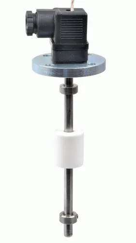
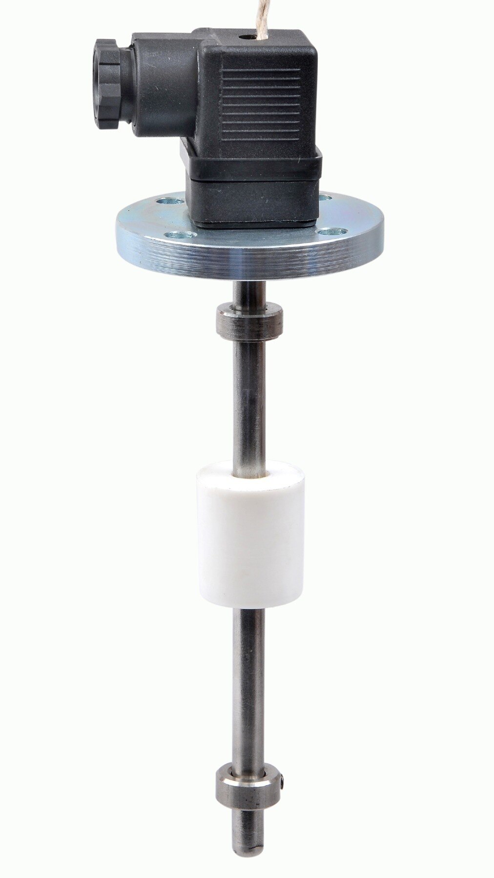
 | Level Transmitter Hydrostatic liquid level transducers and transmitters with flush diaphragm is designed fora wide variety of level measurement applications. View product → |
Frequently asked questions
What does a level transmitter pressure rating mean?
It is the pressure the transmitter’s physical pressure boundary can contain at the process connection. It is not the calibrated level or pressure measuring range.
How do you calculate the highest pressure at a level transmitter?
Add vessel operating pressure, liquid static head, startup or shutdown pressure changes, and credible pressure spikes at the transmitter location. Check the result at the maximum process temperature.
Should you use gauge, absolute, or differential pressure?
Use gauge pressure for measurements referenced to atmospheric pressure, absolute pressure when vacuum or atmospheric changes matter, and differential pressure when comparing tank pressure with liquid head.
What parts of the assembly must share the pressure rating?
Check the process connection, diaphragm or sensing element, body, flange, valves, impulse tubing, seals, manifolds, and fittings. The weakest pressure boundary controls the safe assembly rating.
What should you record before ordering a level transmitter?
Record maximum and normal pressure, design temperature, fluid density, measuring span, reference pressure, process connection, materials, pressure transients, and required certifications.