A level sensor can appear to fail when the liquid never reaches its sensing point, the instrument has lost power, or the PLC is misreading a healthy signal. By checking the actual level, installation, electrical output and control-system input in order, you can identify the fault before recalibrating or replacing the sensor.
Key takeaways
- Confirm liquid reaches the sensor’s physical sensing point.
- Measure supply voltage and signal at the sensor and PLC.
- Match the fault to the sensor type and process conditions.
- Isolate the failed component before recalibrating or replacing it.
First confirm that liquid reaches the sensing point
A level sensor not detecting liquid may be working correctly if the liquid has not reached its sensing point. Compare the actual liquid height with the sensor’s physical elevation, not only the tank’s sight-glass scale or PLC percentage.
A probe mounted above the outlet, a float blocked beneath an internal ledge, or a transmitter aimed above the maximum fill level will remain inactive while liquid is present elsewhere in the tank.
Check these sensor-specific conditions:
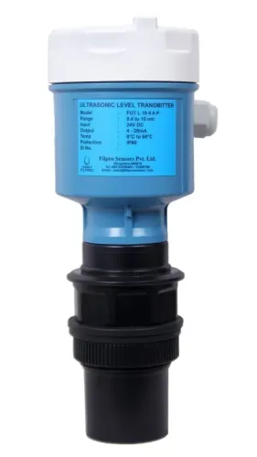
- For an ultrasonic or radar transmitter, confirm that the liquid surface is outside the instrument’s near zone or blocking distance. A sensor mounted too close to the highest level cannot measure that surface reliably.
- For a conductive probe, confirm that the liquid completes a circuit to the vessel ground or reference electrode. Deionized water, oil, hydrocarbons, an insulated vessel, or coating on the probe can leave the circuit open.
- For a capacitance probe, check the probe calibration, vessel bonding, liquid dielectric properties, and buildup. The liquid must change capacitance enough to cross the switching threshold.
Inspect the installation for an inlet stream, agitator, heating coil, ladder, support, tank wall, or heavy turbulence beside the sensing point. These can block the probe or create a false surface; move the sensor to a calmer position or use a stilling arrangement.
If the local indicator shows liquid, compare its diagnostic status with the PLC value, alarm state, and configured range before changing calibration.
Check power, wiring and the signal at both ends
When a level sensor is not detecting liquid, separate a sensing fault from a signal-path fault. Record the local indication and diagnostic or echo-quality status, then compare them with the PLC value, engineering-unit range, display, relay state and alarm status.
A correct local reading with a wrong PLC value indicates scaling, forced or simulation mode, wiring, or a latched alarm.
Check the electrical path in this order:
- Measure supply voltage directly across the sensor’s power terminals, then at the receiving device. A missing voltage, reversed polarity, blown fuse or excessive loop resistance stops a healthy sensor from reporting.
- Inspect terminal tightness, cable continuity, shield termination, common connection and shorts between conductors. Trace the same pair from the sensor to the input; do not assume wire colours match.
- For a 4–20 mA output, measure loop current in series at the sensor end and again at the input end. The readings should match; an open circuit, incorrect load or input fuse creates a difference.
- For 0–10 V DC or 0–5 V DC, measure signal-to-common at both ends. A correct sensor voltage with a wrong input voltage identifies cable or termination loss.
- For RS-485, measure A-to-B differential voltage and verify polarity, common reference and termination; for RS-232, check transmit, receive and signal ground.
Finally, inject a known 4, 12 or 20 mA signal, or the specified voltage, at the receiving input. If the PLC responds, test the sensor separately; if it does not, fix the input or configuration before recalibrating.
Match the symptom to the sensor technology and process
A level sensor not detecting liquid can reflect a mismatch between the sensor’s detection principle and the liquid, or a mechanical fault that prevents the sensing element from responding. Match the symptom to the technology before replacing the instrument.
| Technology | What prevents detection | Result |
|---|---|---|
| Conductive point probe | Deionized water, hydrocarbons, oil, a missing vessel ground, or an insulated coating on the probe | The liquid cannot complete the sensing circuit, so the probe stays dry |
| Capacitance probe | Low-dielectric liquid, a poorly bonded nonconductive vessel, incorrect calibration, or product buildup on the probe | Capacitance does not cross the switching threshold |
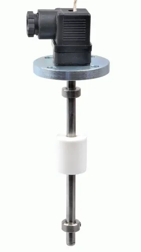
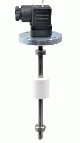
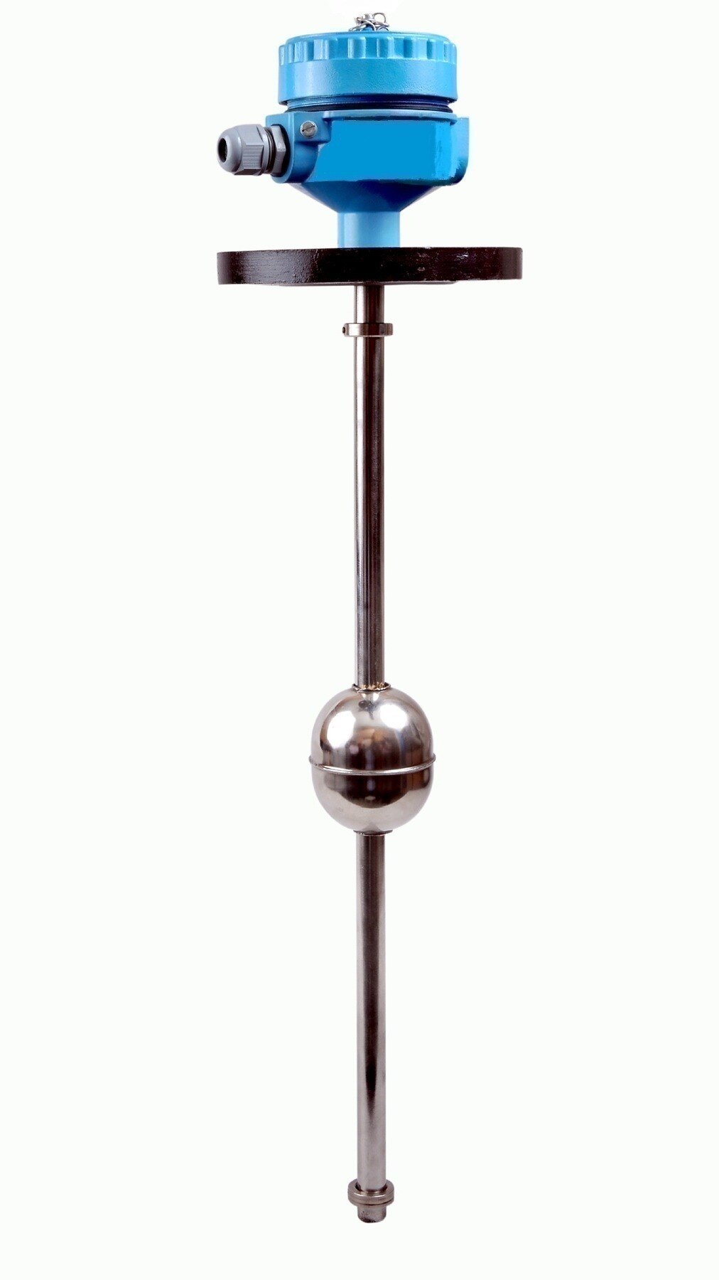
| Float, displacer, or magnetic switch | Solids, wax, crystals, high viscosity, corrosion, or a damaged guide tube | The mechanical element remains in its dry-position state |
| Differential-pressure transmitter | Changed density, stratification, entrained gas, a plugged impulse line, wrong wet-leg fill, or condensation | Hydrostatic pressure no longer represents the actual level |
Temperature and pressure outside the instrument’s rating can cause intermittent output or permanent damage. Temperature also changes viscosity, dielectric behaviour, density, vapour formation, and condensation, explaining why a sensor worked during commissioning but fails in operation.
Compare the local display and diagnostic status with the 4–20 mA value, PLC input, alarm state, and engineering-unit range. A healthy sensor can appear faulty when the PLC is mis-scaled, the input is forced or simulated, or a high/low alarm remains latched.
Separate a failed sensor from a PLC or alarm-system fault
A level sensor not detecting liquid may be working correctly while the control system reports an empty tank. Compare the instrument’s local indication and diagnostic status with its actual output, the PLC input value, the display reading, and the alarm state. A mismatch identifies the fault location.
- If the instrument shows “wet” or a valid level but the PLC shows empty, check the configured 4–20 mA range, input scaling, polarity, and whether the channel is in simulation or forced mode.
- For a point switch, verify whether the output is normally open or normally closed, whether the PLC expects inverted logic, and whether fail-safe action changes a diagnostic fault into an empty indication.
- Check the alarm trip direction, hysteresis, and latch separately. A high-level alarm configured as low-level, or an uncleared latched alarm, can misreport a correct sensor.
- Compare the relay output and display with the PLC value. If the sensor output changes but the relay or display does not, isolate that device or its input channel.
Test the instrument with a controlled wet/dry change or a calibrated signal simulator, then observe its output at the receiving device. For an ultrasonic or radar unit, review echo quality and blocking-distance settings; liquid inside the near zone can produce no valid reading. Recalibrate only after the sensor and signal path agree.
Recalibrate or replace only after the fault is isolated
Before recalibrating a level sensor not detecting liquid, collect evidence that distinguishes a sensing fault from an installation, configuration, or process fault. A new calibration can hide the cause and create a second baseline that nobody can defend.
1. Record the liquid level from an independent sight glass or manual measurement, plus the sensor’s local value, diagnostic code, echo-quality reading, and event time. Photograph the mounting position, process connections, obstructions, and any ultrasonic or radar near-zone clearance.
2. Compare the instrument’s actual output with the receiving value: 4–20 mA current or voltage, PLC engineering-unit value, alarm state, and configured range. Save the configuration, including output inversion, normally-open or normally-closed selection, fail-safe action, hysteresis, simulation or forced mode, and alarm latch status.
3. Run a controlled wet/dry or simulated-input check and document the response. For differential-pressure instruments, record density, temperature, impulse-line condition, wet-leg fill, entrained gas, and condensation; each can distort inferred level without a failed transmitter.
Replace the instrument only when these checks show a repeatable sensor-side fault. Choose a different technology or mounting arrangement when turbulence, an obstruction, blocking distance, density changes, or stratification defeats the present measurement principle.
Ask Filpro Sensors Pvt Ltd or the original manufacturer for a technical review when the evidence conflicts, the process is hazardous, or replacement requires a new connection, range, or installation position.
Related products
 | Level Transmitter Hydrostatic liquid level transducers and transmitters with flush diaphragm is designed fora wide variety of level measurement applications. View product → |
 | Level Transmitter Float Level Transmitters Are Ideal For Continuous Level Monitoring In Water, Diesel, Chemical And Oils For Accurate Level Measurement. View product → |
Frequently asked questions
What should you check first when a level sensor is not detecting liquid?
Confirm that the liquid has reached the sensor’s physical sensing point. Compare the actual liquid height with the sensor elevation rather than relying only on a sight-glass scale or PLC percentage.
How can you tell whether wiring or power is causing the fault?
Check the sensor’s supply voltage, terminal connections and cable continuity, then measure the output at the sensor and again at the PLC input.
How does sensor technology affect troubleshooting?
Match the symptom to the sensor technology and process. Coating, foam, turbulence, density, conductivity, temperature and installation position affect different sensor types in different ways.
How do you separate a failed level sensor from a PLC fault?
Compare the signal at the sensor terminals with the signal received by the PLC. A correct sensor output with an incorrect PLC reading points to wiring, input configuration or the alarm system.
When should you recalibrate or replace a level sensor?
Recalibrate or replace the sensor only after confirming the liquid reaches the sensing point and isolating power, wiring, signal, PLC and process-related causes.
Related products
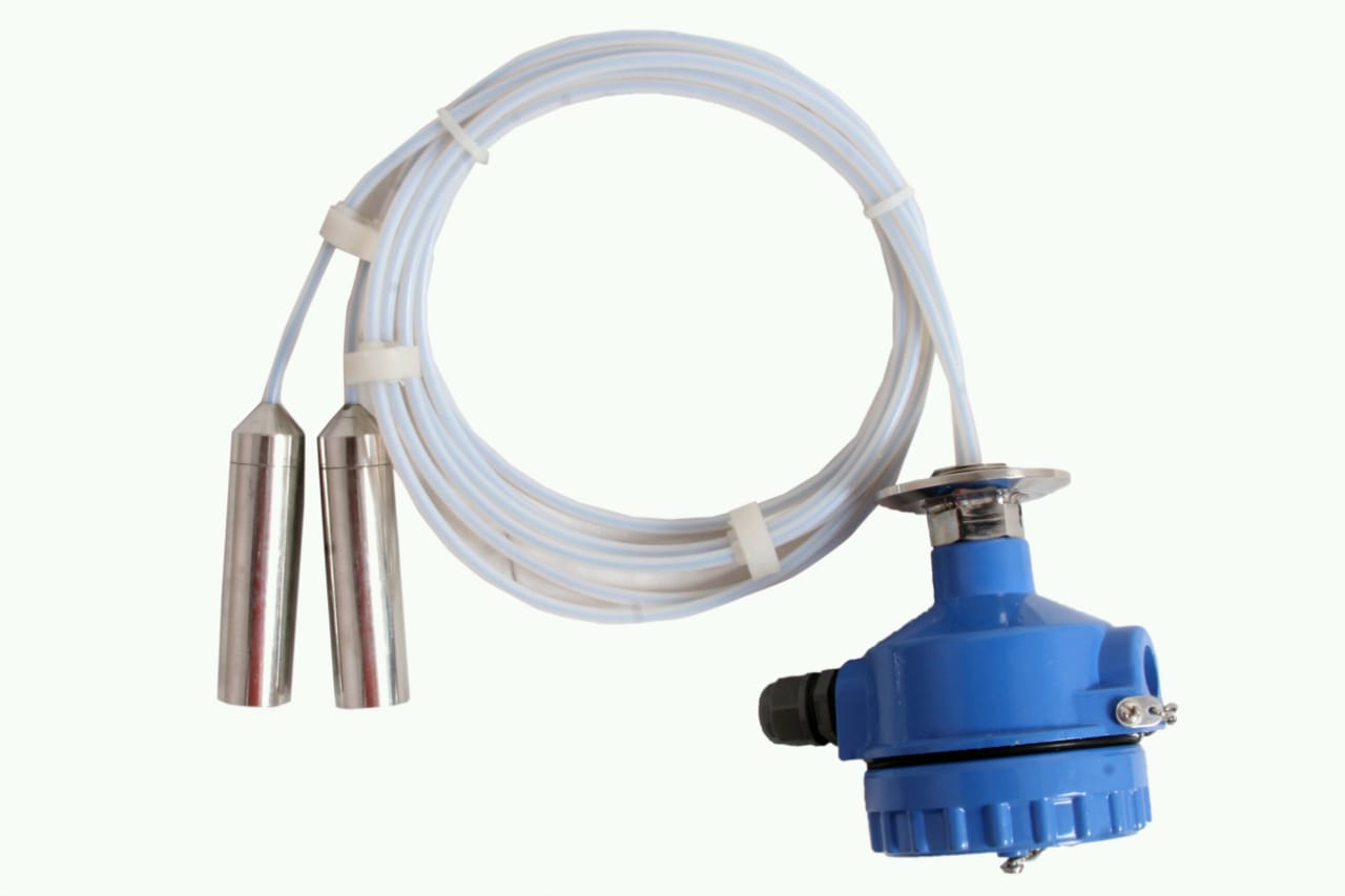 | Level Transmitter can be used for conductive as well as non conductive liquids. View product → |
 | Level Switch Filpro offers most reliable, cost effective Side Mounted Level Switch for point level sensing. View product → |
 | Level Transmitter Ultrasonic Level Sensor is a non-contact ultrasonic continuous level measurement product based on sound technology. View product → |
 | Level Sensor Atex approved Float Level Transmitter : Over All Length: 300mm to 5000mm Input: 16V DC to 30V DC Output: 4-20mA / 0-10V DC Resolution: 5mm / 10mm... View product → |