A reliable calibration starts by identifying whether you are testing a point-level switch, a continuous transmitter, or the complete control loop. You will learn how to establish true level references, set low and high thresholds or 4–20 mA scaling, verify fail-safe operation, and document the result without confusing a display adjustment with a sensor correction.
Key takeaways
- Identify the sensing technology before selecting a calibration method.
- Use measured, traceable level references instead of relying on tank markings.
- Test both pump switching points and the controller’s switch-back logic.
- Record 4–20 mA output at zero, midpoint, and full-scale levels.
Identify the sensing technology and the calibration task
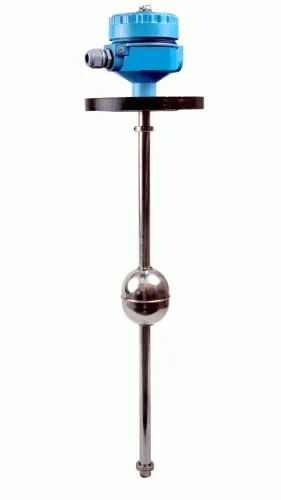
Before changing parameters in liquid level controller calibration, identify the sensing technology and the task being calibrated. Classify the instrument as a magnetic float switch, cable float switch, side-mounted switch, float transmitter, hydrostatic transmitter, or ultrasonic transmitter.
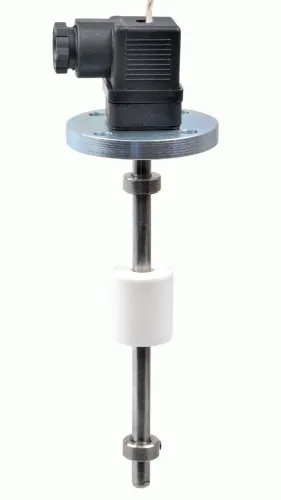
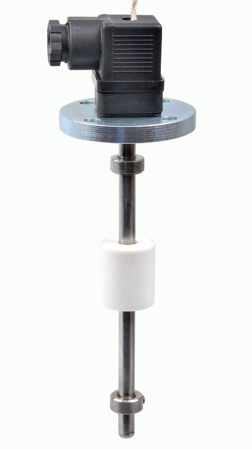
1. Test the sensing element. A fixed-contact float switch needs a switch-point, deadband, alarm-state, and reset test as the float rises and falls. It does not receive a conventional pressure zero-and-span adjustment. A failed switch-point test can conceal an untested pump or safety function.
2. Check transmitter input and output. For a 4–20 mA float or other continuous transmitter, verify the measured range, lower range value, upper range value, and current output against known levels. Trimming the output will not correct an incorrectly entered tank range.
3. For a hydrostatic transmitter, calculate the pressure range from ΔP = ρgh using the liquid density at operating temperature. Check pressure-tap elevations, vapor reference, wet leg, and remote-seal configuration; a closed tank normally connects the low-pressure side to the vapor space. Adjusting displayed level will not repair a faulty pressure-to-level conversion.
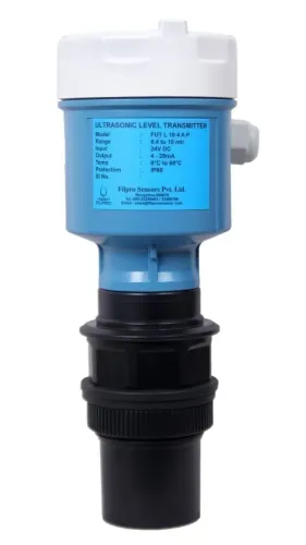
4. For an ultrasonic transmitter, use the manufacturer’s reference point, such as the transducer face, and verify tank height, empty distance, full distance, and blocking distance. Foam, condensation, ladders, nozzles, or a false bottom can create a stable but wrong echo, which an offset change will not reliably fix.
5. Verify the controller loop by applying known levels and confirming the displayed value, thresholds, alarm actions, and final output. Save parameters only after every response matches the intended operating levels.
Create safe, traceable level references before calibration
Establish the reference by tying each controller reading to a known physical level, pressure, or independent instrument reading. For liquid level controller calibration, define the tank datum: the physical zero point from which level is measured. Record these details before changing anything:
- Instrument tag, serial number, range, engineering units, as-found readings, process temperature, liquid density, current settings, reference-equipment identification, and pass/fail limits.
- The usable height separately from total tank height. A 3,000 mm vessel may contain a 200 mm dead zone and have a 2,500 mm configured measurement span.
Apply lockout/tagout under OSHA 29 CFR 1910.147 when isolation or access involves hazardous energy. Isolate pumps and valves, depressurize a pressurized vessel, and verify that the manifold, impulse lines, seals, and pressure source are rated for the applied test pressure.
Use a dip tape, sight glass, calibrated tank volume, gauge board, or independent reference transmitter to establish actual level. A dry pressure check verifies the transmitter, not plugged lines, leaking fittings, wrong manifold positions, vapor pockets, or seal-liquid errors.
For a hydrostatic device, calculate ΔP = ρgh using the actual liquid density at operating temperature. Include tap elevation, wet-leg head, or seal-liquid head when calculating the LRV and URV.
| Installation | Low-pressure reference | Range calculation | Main risk |
|---|---|---|---|
| Open tank | Atmosphere | Liquid head from the datum to each test level | Incorrect density creates proportional level error |
| Closed tank | Vapor space | Liquid head plus tap, wet-leg, or seal-liquid head | A missing vapor connection makes vessel pressure appear as level |
Calibrate a two-point pump controller and verify its switching logic
Liquid level controller calibration for a two-point pump controller means proving that the low-level stop and high-level start occur at the approved liquid heights, not merely that the display changes. Isolate the tank, pump, and control circuit before making adjustments, and use the dip tape, sight glass, or gauge board to establish each reference.
1. Set the liquid at the low-level stop point by adding or removing liquid. Confirm that the switch changes state, then enter the corresponding stop parameter if the controller provides one.
2. Set the liquid at the high-level start point, confirm the opposite switching action, and save the start parameter. Cycle the level through both thresholds, allowing the configured settling time before recording each result.
3. Check the deadband. A pump that starts at 1,500 mm and stops at 500 mm has a 1,000 mm separation that prevents rapid cycling.
4. For a float switch with fixed contacts, test mechanical movement and electrical continuity at each specified point. Check rising and falling levels separately because float friction, cable movement, and switch hysteresis can produce different start and stop heights.
| Control check | Direct action | Reverse action |
|---|---|---|
| Rising level | Output follows the configured start response | Output follows the configured stop response |
| Lost or broken signal | Confirm whether the relay commands fail-safe stop or start | Confirm whether the relay commands fail-safe stop or start |
| Alarm override | Verify high-high and low-low alarms interrupt normal control when specified | Verify high-high and low-low alarms interrupt normal control when specified |
Restore guards, valves, pump power, and automatic mode only after the output matches the approved operating sequence.
Calibrate a continuous 4–20 mA level transmitter across the range
Begin liquid level controller calibration by recording the configured zero and span from the transmitter manual and controller configuration. Do not assume that zero means an empty tank or that full scale means the vessel’s nominal capacity.
For a 0 mm to 2,000 mm range, 4 mA represents 0 mm and 20 mA represents 2,000 mm.
Apply or observe these reference levels, then allow the configured damping or filter time to settle before recording results:
| Reference level | Expected transmitter output | Controller input and displayed value |
|---|---|---|
| 0 mm (0%) | 4 mA | 0 mm |
| 500 mm (25%) | 8 mA | 500 mm |
| 1,000 mm (50%) | 12 mA | 1,000 mm |
| 1,500 mm (75%) | 16 mA | 1,500 mm |
| 2,000 mm (100%) | 20 mA | 2,000 mm |
Measure loop current in series with a properly rated loop calibrator. Never connect a conventional ammeter across the loop; it can short the supply. Compare transmitter output, controller input, and displayed engineering value independently, because a correct transmitter can feed a mis-scaled input.
For a hydrostatic transmitter, a dry pressure-calibrator test verifies the pressure range, not plugged impulse lines, vapor pockets, leaking fittings, manifold position, or seal fill. Complete it with a wet or operational check. For ultrasonic devices, verify the antenna or transducer reference face, echo quality, blocking distance, foam, condensation, and internal obstructions.
Keep sensor trim, analog-output trim, and controller input scaling as separate adjustments.
Verify the control loop, return it to service, and keep the record
After the measurement passes, prove the complete loop: change the process variable, confirm the controller response, and verify that the pump, valve, or other final element takes the intended action.
| Check | Verify | Failure exposed |
|---|---|---|
| Control action | Direct or reverse action, setpoint units, output limits | Level rises when it should fall, or vice versa |
| Configuration | Split-range or cascade settings and alarm priorities | A valid signal reaches the wrong output or alarm |
| Final element | Pump or valve movement and fail position | The vessel overfills or empties during signal loss |
Test increasing and decreasing level points. The difference reveals hysteresis, float or displacer friction, filtering, valve-positioner delay, or sluggish pump response. Allow the configured settling time before recording each point; reducing intentional damping can improve response but increase nuisance cycling.
Restore the installation in a controlled sequence:
- Re-establish process isolation, manifold valves, impulse lines, covers, and power.
- Confirm no leaks, then place the controller in automatic mode.
- Observe one complete operating cycle, including the alarm and final-element response.
Record the instrument tag and serial number, range and units, reference levels, applied pressure or liquid conditions, current readings, reference-equipment identification and accuracy, settling time, adjustments, pass/fail criteria, and as-found and as-left values. Without as-found data, you cannot distinguish service drift from maintenance adjustment.
For future liquid level controller calibration, Filpro Sensors Pvt Ltd can clarify the installed instrument’s range, sensing technology, reference datum, output scaling, wetted materials, and recommended verification method.
Related products
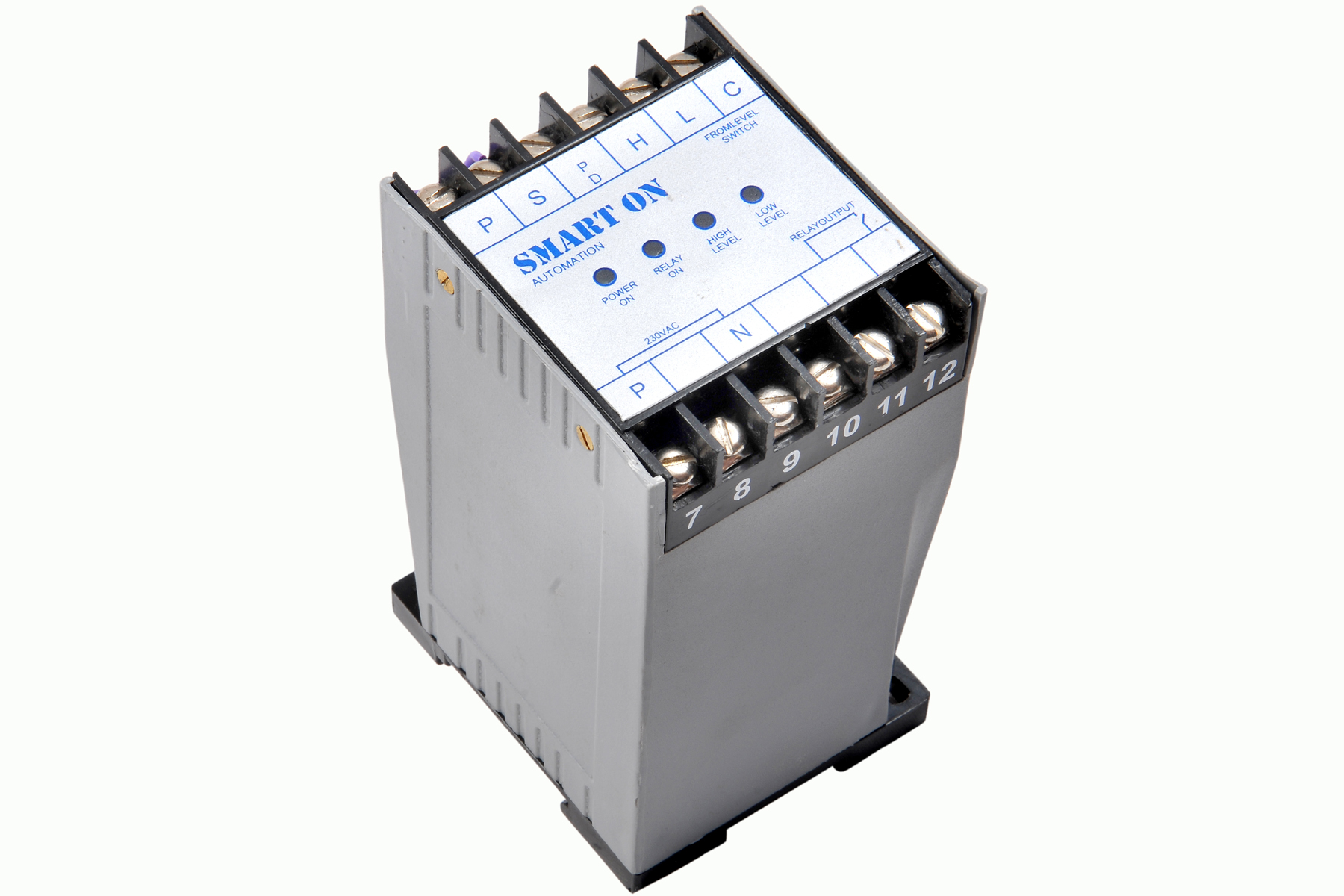 | Controller Filpro Sensors Pvt Ltd manufactures industrial Level Controller (Smart On) to automatically start & stop the pump. View product → |
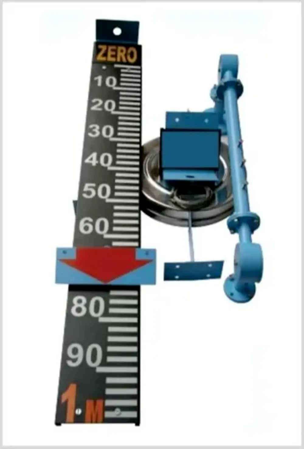 | Level Indicator The Float & Board Level Indicators consists of a float connected to a pointerthrough a rope via a set of pulleys. View product → |
Frequently asked questions
How do you identify the calibration task for a liquid level controller?
Identify whether the instrument is a magnetic float switch, cable float switch, side-mounted switch, float transmitter, hydrostatic transmitter, or ultrasonic transmitter. Then define whether you are calibrating switching points, displayed level, analogue output, or the complete control loop.
How do you create a safe level reference before calibration?
Isolate the equipment, follow the site permit and lockout procedure, and establish measured low and high reference levels with a calibrated dipstick, sight glass, stilling well, or verified test vessel. Record the reference method and instrument used.
How do you calibrate a two-point pump controller?
Apply the low-level reference and adjust the stop or start threshold specified for the process. Apply the high-level reference, adjust the opposite threshold, then cycle the level through both points to verify pump start, pump stop, alarm action, and hysteresis.
How do you calibrate a continuous 4–20 mA level transmitter?
Apply the defined zero and full-scale level references, set the transmitter to 4 mA and 20 mA, and check intermediate points such as 25%, 50%, and 75%. Confirm the receiving display or PLC shows the same scaled level.
What should you verify before returning a calibrated controller to service?
Check wiring, power, valve and pump operation, alarm states, fail-safe action, and the complete control-loop response. Record as-found and as-left readings, reference levels, adjustments, date, technician, instrument identification, and next due date.
Related products
 | Level Transmitter Float Level Transmitters Are Ideal For Continuous Level Monitoring In Water, Diesel, Chemical And Oils For Accurate Level Measurement. View product → |
 | Level Switch Filpro offers most reliable, cost effective Side Mounted Level Switch for point level sensing. View product → |
 | Level Transmitter Hydrostatic liquid level transducers and transmitters with flush diaphragm is designed fora wide variety of level measurement applications. View product → |
 | Level Sensor Atex approved Float Level Transmitter : Over All Length: 300mm to 5000mm Input: 16V DC to 30V DC Output: 4-20mA / 0-10V DC Resolution: 5mm / 10mm... View product → |