Foam can make a transmitter report the foam top, a liquid–foam boundary, or an unstable internal echo instead of the liquid inventory you need. By defining the measurement target, characterising the process, choosing the right technology and testing the complete installation, you can separate a usable level signal from a misleading one.
Key takeaways
- Define whether you need foam height, liquid level, interface, or total inventory.
- Use radar, ultrasonic, capacitance, or differential pressure based on foam and vessel conditions.
- Aim the sensor at the intended interface and configure false-target suppression carefully.
- Test failure alarms, verify readings against a reference, and specify every installation detail.
Define which level you need before choosing the transmitter
Before choosing a level transmitter for foam liquids, define whether you need the foam’s upper surface, the liquid beneath it, the foam-layer height, or the vessel’s actual inventory. Radar and ultrasonic instruments can lock onto any of these surfaces, so “level” is not a sufficient procurement description.
| Target | What it means | Choose it when |
|---|---|---|
| Top-of-foam level | Height of the foam’s upper boundary | You need to control foam carryover, residence space, or visible froth |
| Collapsed-liquid level | Liquid–foam boundary after foam collapse | You need process liquid volume rather than apparent vessel filling |
| Foam-layer height | Distance between the liquid boundary and foam top | You need to manage foaming, separation, or dosing performance |
| Total vessel inventory | Actual liquid quantity, usually converted to volume or mass | You need material balance, batching, or stock control |
State the target in the instrument specification and define how foam density, thickness, collapse, agitation, vapour, and temperature will vary. A transmitter’s stated accuracy applies to its detected interface; it does not cover a false surface, changing foam density, probe coating, or installation echoes.
For overfill protection, do not rely on one foam-sensitive continuous transmitter. Add an independent high-high switch using a different measurement principle or sufficiently independent installation, then proof-test it under your site’s safety procedure.
If you choose differential pressure, remember ΔP = ρgH. Foam’s density changes as bubbles form and collapse, so calibrating with bulk-liquid density converts foam variation into level error. On a closed vessel, keep the wet reference leg or remote seal at a known, stable density; condensation, evaporation, plugging, or foam entry will imitate process movement.
Match the foam and vessel conditions to a measurement technology
Choose technology by foam stability, vessel geometry, and the liquid interface you need to track; no single level transmitter for foam liquids suits every tank.
| Technology | Best fit | Main risk or check |
|---|---|---|
| Guided-wave radar | Foam layers with a probe path and a stable dielectric contrast | Multiple reflections from foam and liquid can create false interfaces. Check probe length, buildup, anchoring, agitators and internals. |
| Non-contact radar | Tall, hot, pressurised or vapour-filled vessels with moderate foam | Foam can weaken the return or create a false echo. Select antenna size, frequency, beam angle and echo mapping from the vessel geometry, not range alone. |
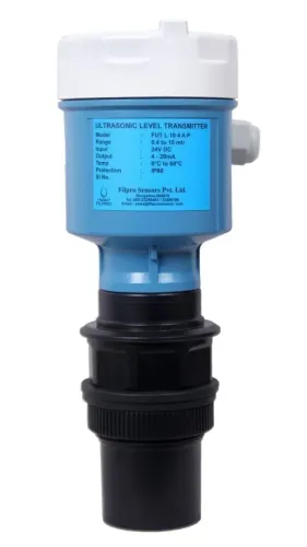
| Ultrasonic | Calm vessels containing little, weak, collapsing foam | Foam scatters and absorbs sound, causing lost echoes or readings that follow foam texture. Do not choose it merely because the liquid is corrosive. |
| Hydrostatic | Liquids with stable density and little foam across the sensing height | Foam has lower, changing density. Calibrating with bulk-liquid density turns foam-height changes into level error. |
| Capacitance | Liquids with a consistent dielectric contrast and manageable probe coating | Variable foam density, changing dielectric constant and buildup can shift the apparent level. |
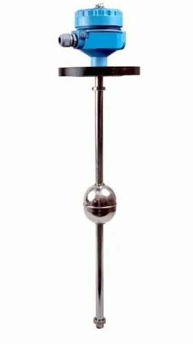
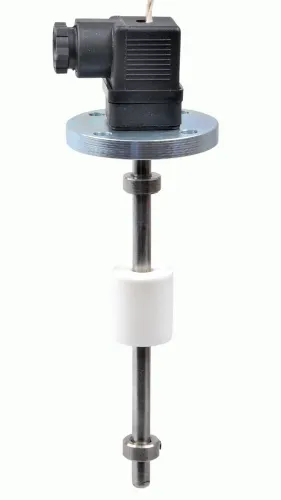
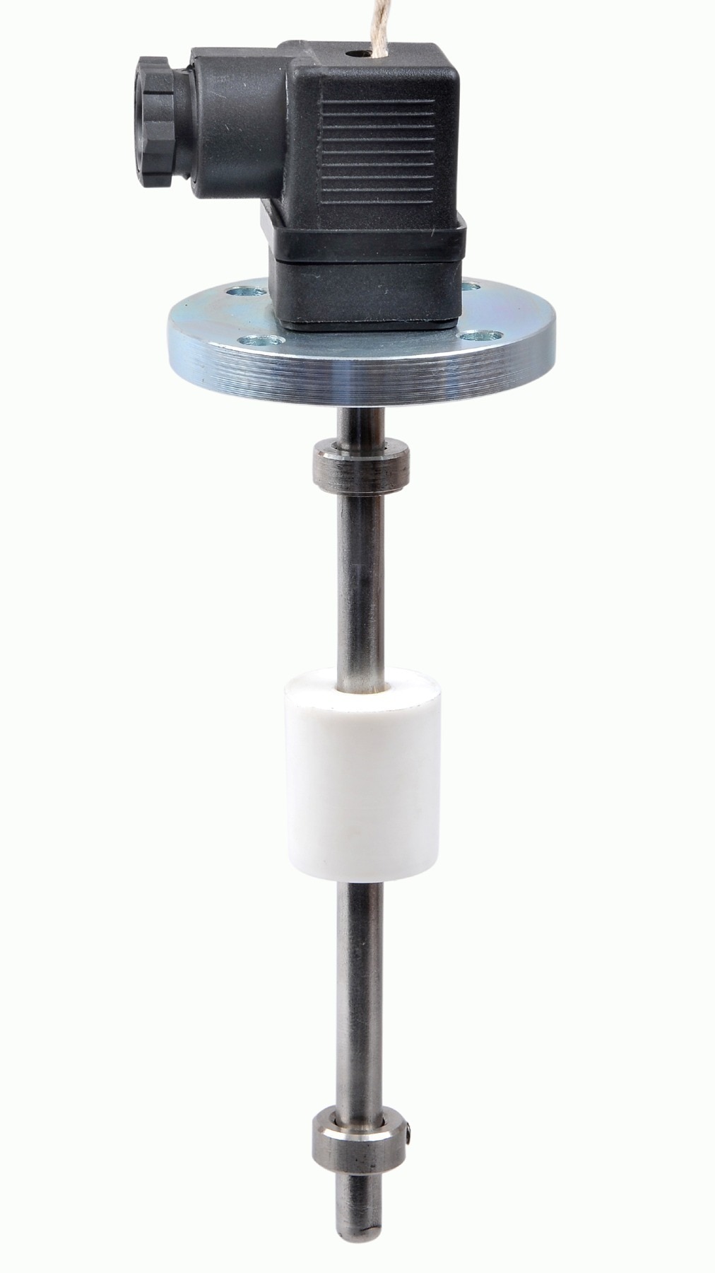
| Float | Simple, accessible tanks where foam cannot support, bridge or obstruct the float | Sticky foam can hold the float high, while turbulence and guide friction delay movement. |
A stilling well can steady radar or float readings, but foam may enter through openings, bridge there or drain at a different rate from the vessel. Verify the well against filling, draining and agitation conditions before treating it as an improvement.
Install and configure the transmitter so it sees the intended interface
Mount the level transmitter for foam liquids where its antenna or probe has a clear path to the intended interface, away from inlet jets, agitator blades and heating coils.
Keep the nozzle above the expected foam zone when measuring collapsed liquid; use a stilling well or bypass only when it will not trap foam, vapour or condensate.
Mark these details on the installation drawing before cutting the nozzle:
- Expected foam-zone height and the required measurement interface
- Nozzle elevation, antenna or probe orientation, and clearance from the vessel wall
- Agitator blades, inlet jets, heating coils and surfaces that can create echoes
- Vapour-condensation paths, wash sprays and the cleaning method
- Access for removing buildup from the antenna, probe or stilling arrangement
Configure the false-echo map only after commissioning with the vessel empty and with known obstructions present. Set damping, echo-loss timeout and alarm delays against the actual filling, foam-generation and collapse sequences; excessive damping or echo rejection can hide a rapid level rise. Test the result during production, not only with clean water.
Separate transmitter accuracy from total installed uncertainty in the procurement specification. Include foam thickness, coating, installation echoes and interface changes. For closed-vessel DP measurement, keep the wet reference leg or remote seal at a known stable density; condensation, evaporation, plugging or foam entering the reference side creates a false level.
Use an independent high-high switch for overfill protection and proof-test it under site safety procedures.
Prove the measurement and protect the process when the signal fails
Validate a level transmitter for foam liquids against an independent reference, then make every dangerous failure drive the process to a defined state. Use a sight glass, dip measurement, load-cell inventory or a second level instrument during filling, steady operation and draining; record the foam height and collapsed-liquid level at each check.
1. Confirm what the signal represents. A reading that rises with foam height is not proof of increased liquid inventory. Compare the transmitter with the chosen reference at several levels and document the difference as installed uncertainty, separate from the instrument’s stated accuracy.
2. Check the diagnostic display and trend. Ultrasonic echo loss, excessive damping and rapid changes that follow foam texture indicate acoustic failure. Radar alarms, weak returned echoes or a new false echo indicate attenuation or surface confusion. A capacitance reading that drifts after foam contacts the probe indicates coating or a changing dielectric constant.
3. Test the output path. Command a known value or use the manufacturer’s loop test, then verify the control system receives it. A frozen value, unchanged current during a changing reference level or a failed communication heartbeat requires a fault alarm, not continued automatic control.
4. Set independent high and high-high alarms with time delays shorter than the credible overfill window. Configure loss of power, signal, diagnostic fault and out-of-range current to a documented safe state.
5. Use a separate high-high switch for overfill protection, with a different measurement principle or independent installation. Proof-test it at the interval required by your site safety procedure; do not treat a passing continuous reading as proof of protection.
Specify the complete installation before ordering
Specify the complete installation before ordering a level transmitter for foam liquids: define the measurement target, vessel conditions, connection, signal, hazardous-area classification and maintenance plan in one purchase specification.
1. Record the process data: top-of-foam, collapsed-liquid or inventory level; measuring range; foam thickness, density, bubble stability and conductivity; liquid density and dielectric constant; temperature, pressure, vapour, agitation, filling and draining behaviour. State the required total installed uncertainty separately from the transmitter’s interface accuracy.
2. Describe the mechanical installation: vessel diameter and height, nozzle size and orientation, available insertion length, internal coils or agitators, expected buildup, wetted-material requirements, gasket material, pressure rating and access for removal.
For DP, document whether the reference leg is wet or remote-seal, its fill fluid and the conditions that could cause condensation, evaporation or plugging.
3. Specify the electrical and safety requirements: supply voltage, output such as 4–20 mA, communication protocol, alarm action, cable entry, grounding and enclosure rating. Give the hazardous-area zone, gas group, temperature class and required certification; do not leave these to catalogue selection.
4. Define maintenance: cleaning frequency, calibration access, spare parts, inspection points and proof-test interval. If overfill protection is the objective, specify an independent high-high switch with a separate measurement principle or installation.
Filpro Sensors Pvt Ltd can check the specification against nozzle geometry, foam behaviour, signal requirements and hazardous-area documentation, then flag conflicts before manufacture. Ask for a dimensional installation drawing, uncertainty assumptions and a commissioning checklist—not just a model number.
Related products
 | Level Transmitter Ultrasonic Level Sensor is a non-contact ultrasonic continuous level measurement product based on sound technology. View product → |
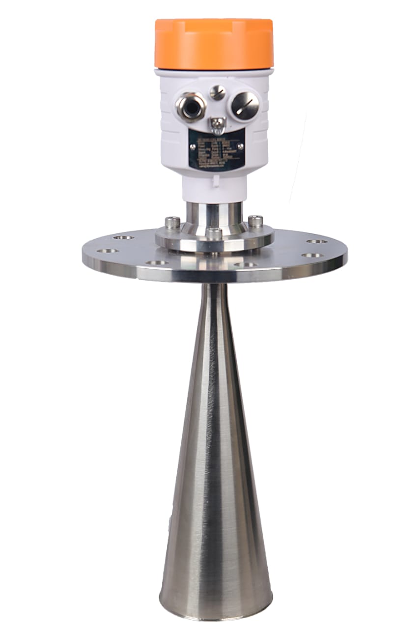 | Level Transmitter FILPRO offers professional Radar Level Transmitter. Our radar level transmitter uses radar to continuously measure non-contact liquid level, the... View product → |
Frequently asked questions
What level should you measure in a foaming vessel?
Define whether you need the foam’s upper surface, the liquid beneath it, foam-layer height, or actual vessel inventory before selecting a transmitter.
Which measurement technology works for foam liquids?
Match radar, ultrasonic, capacitance, or differential-pressure measurement to the foam structure, dielectric properties, vessel geometry, temperature, pressure, and installation conditions.
How do you install a transmitter so it measures the intended interface?
Position the instrument away from inlets, agitators, coils, and obstructions; aim it at the required surface; then configure blocking distance, false-target handling, damping, and range.
How do you verify a foam level transmitter and handle signal failure?
Compare the transmitter with a trusted manual or independent measurement, test alarm states and sensor diagnostics, and define the process response for lost or invalid signals.
Related product
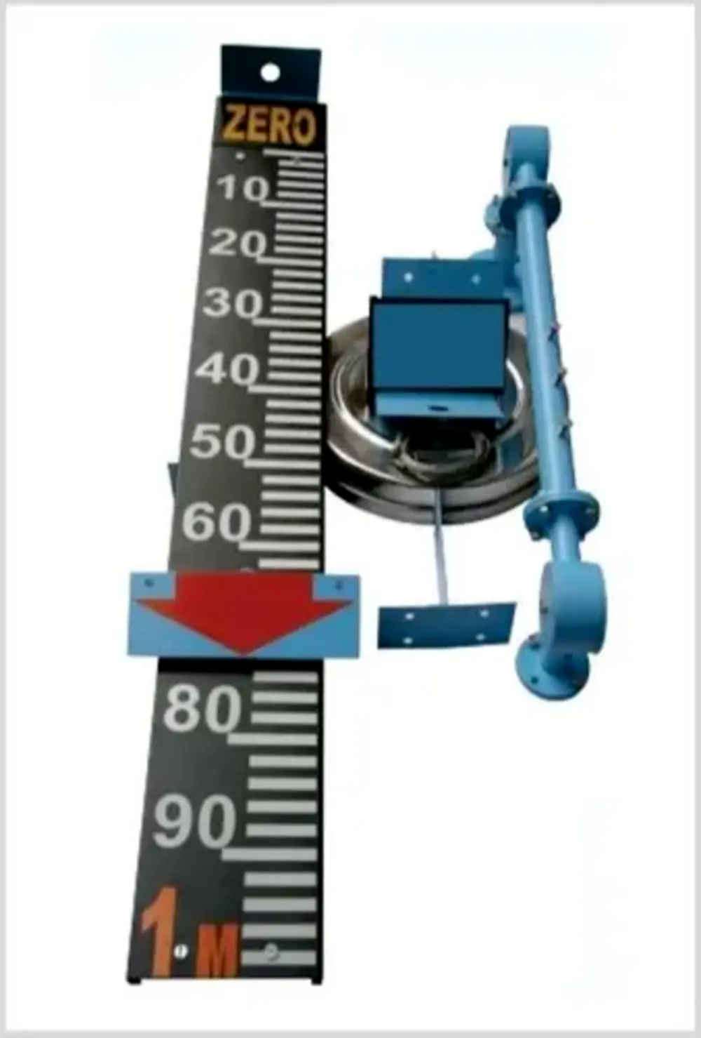 | Level Indicator The Float & Board Level Indicators consists of a float connected to a pointerthrough a rope via a set of pulleys. View product → |