A wrong level indication can come from the sensor, the installation, the process, the signal wiring or the display that receives the signal. By comparing the reading with an independent measurement and classifying the error pattern, you can isolate the fault before recalibrating or replacing a working instrument.
Key takeaways
- Verify the reading with a dip, sight glass or load-cell measurement.
- Compare empty, mid-range and full readings to identify the error pattern.
- Inspect mounting, reference points, wiring and buildup before replacing electronics.
- Match corrective tests to radar, ultrasonic, float, hydrostatic or capacitive sensors.
Start with an independent level check
Before changing settings, prove the level sensor detects wrong level with an independent level measurement under the same tank condition and measurement reference. Compare it with a manual dip, functioning sight glass or load-cell tank mass at empty, mid-range and full.
Confirm the sight glass is clear, the dip reaches the actual bottom, and stratification or liquid movement has not created different levels at the comparison points.
- Record the sensor value, reference value, raw process variable and diagnostic status at all three conditions.
- Compare the raw value with the PLC or HMI value. Check 4–20 mA scaling, reversed high and low ranges, percent-versus-engineering-unit conversion, tank-geometry calculations, damping and tag mapping.
- Separate the level sensor troubleshooting into sensor, wiring, configuration and process faults. Measure supply voltage at the instrument terminals, then check loop continuity, polarity, grounding and voltage drop.
- Repeat the comparison while filling and emptying. Turbulence, vortexing, foam, falling product or transport delay can create a real process difference rather than a calibration error.
| Pattern | What it suggests | Next check |
|---|---|---|
| Constant offset | Zero, reference elevation or installation error | Verify the measurement reference and mounting position |
| Changing scale | Incorrect range or tank-geometry calculation | Check sensor configuration and PLC/HMI scaling |
| Noisy reading | Turbulence, foam, wiring interference or unstable echo | Compare during a settled hold |
| Stuck reading | Blocked impulse path, failed signal or configured hold-last-value | Inspect the process connection and diagnostics |
A correct raw value with a wrong HMI value points to configuration, not a failed instrument. This sequence prevents unnecessary recalibration or replacement.
Use the error pattern to narrow the fault
The shape of the error tells you which fault to test next when a level sensor detects wrong level.
| Pattern | What it means | Check next |
|---|---|---|
| Constant level offset | The reading is wrong by roughly the same amount at empty, mid-range and full. | Check zero, mounting elevation, tank datum, reference-head assumption, fixed wiring and configuration. |
| Changing scale error | The discrepancy grows as the tank level rises. | Check span, tank geometry, density, dielectric constant, acoustic speed and a wrongly cut float stem. |
| Noisy level reading | The value moves rapidly around the actual level. | Check turbulence, sloshing, foam, electrical interference, unstable purge pressure, weak echoes and excessive process movement. |
| Stuck level reading | The value stops changing or holds a plausible value. | Check mechanical friction, a blocked acoustic path, invalid echo, failed reed switch, coated probe, excessive damping and hold-last-value settings. |
Check whether the error appears only during filling or emptying. A dynamic-only error points to falling product, vortexing, transport delay, foam or turbulence, not static calibration. For radar, do not apply echo mapping to hide a false echo that appears only as the process changes.
Test the loop with a known current signal. If the display remains wrong, inspect 4–20 mA scaling, reversed range values, percent-to-engineering-unit conversion and the input-channel mapping. Do not increase damping until you know it is not concealing a real level change.
Inspect the installation before blaming electronics
Before blaming electronics, inspect the installation: a level sensor detects the wrong level when its physical measurement no longer matches the tank. An installation error can create a constant, repeatable reading even when wiring, calibration and display electronics work correctly.
For a float or displacer unit, check:
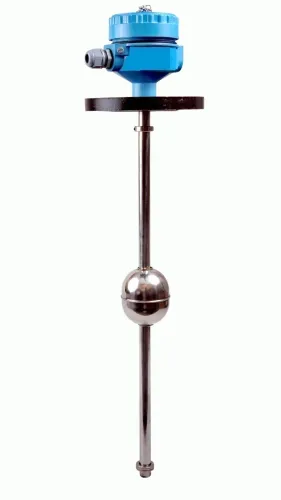
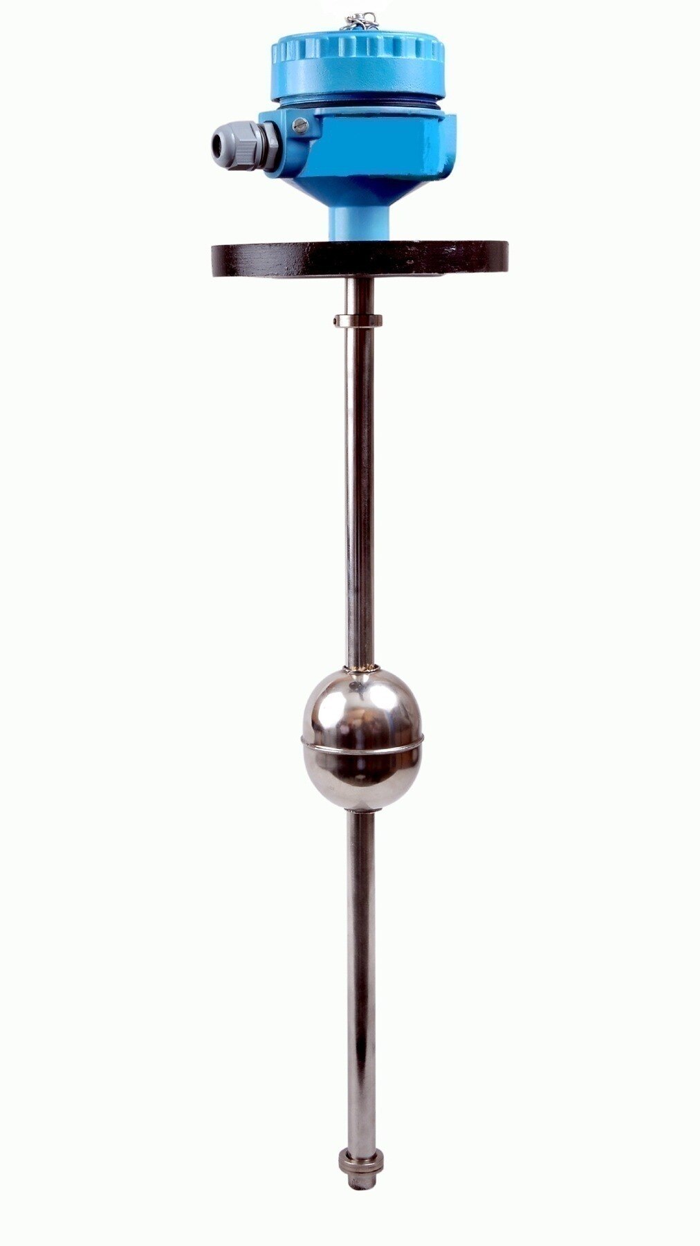
- Stem length against actual tank depth, insertion depth and the mounting datum. A stem cut too short or a sensor mounted above the true bottom creates a fixed offset.
- Float orientation and movement. An upside-down float, bent stem, internal pipe, agitator, heating coil, baffle or tank wall can trap it.
- Float condition. Look for punctures, liquid inside, lost buoyancy and deposits that increase friction. Examine dents or contamination in the guide tube.
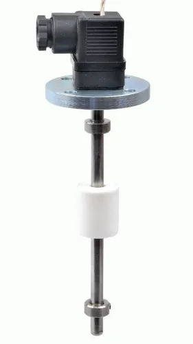
- Reed switches, magnets and magnetic coupling across the full travel. A float sensor fault can leave a plausible value that does not follow movement.
Compare other installation-dependent causes as follows:
| Instrument | Inspect | Result of failure |
|---|---|---|
| Float or displacer | Stem, guide, buoyancy and freedom of movement | Sticking, lag or repeatable offset |
| Hydrostatic or DP | Specific gravity, flush diaphragm, impulse-line slope and elevation | A hydrostatic level error; a coated diaphragm, trapped air, leaking line, blocked vent or unequal vessel pressure shifts the reading. Wet legs need correct reference-liquid height and density; dry legs need condensation protection. |
| Bubbler | Purge flow, leaks, tube blockage and submergence | Back-pressure appears as a false level |
| Capacitance probe | Coating and tank ground | Coating becomes part of the measurement |
| Radar | Wall, fill stream, agitator, nozzle and blocking distance | Reflections or a near-zone blind reading mimic the surface |
Match the fault to the sensing technology
A level sensor detects wrong level when its assumed physical condition no longer matches the tank, even though its electronics pass self-diagnostics. Match the symptom to the sensing method: an ultrasonic false reading usually involves the acoustic path, while a radar level error often involves echo selection or installation geometry.
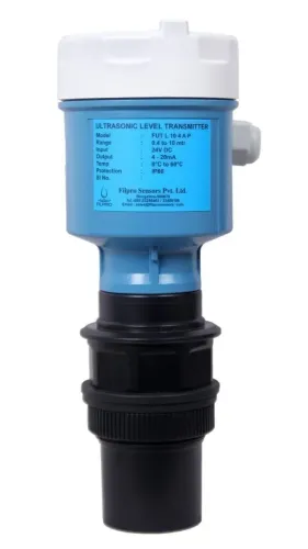
- Ultrasonic: The sensor calculates distance from acoustic time of flight. Gas temperature, vapour, steam, condensation on the transducer, dust, foam, wind, turbulence and a noisy fill stream can weaken or scatter the pulse. Check the acoustic path, tank height and false echoes from ladders, pipes or a narrow, irregular stilling arrangement.
- Non-contact radar: The antenna can lock onto a nozzle, agitator, ladder, weld or support. Check antenna position, wall clearance, fill-stream interference, buildup, foam, low-dielectric liquid, turbulence, echo selection and the configured measurement reference point. Include blocking or near-zone distance when checking a full-tank indication.
- Guided-wave radar: Its probe reduces vapour-space exposure, but coating, bridging to the wall, changed dielectric constant and weak interface contrast can still shift the reading. Inspect the probe and the process around it.
- Capacitance: A changed product dielectric constant or conductive film on the probe changes the measured capacitance. Clean the probe and confirm the configured material properties.
- Interface level measurement: Determine whether the instrument sees the top of an emulsion, its bottom or the denser liquid. Density values alone do not define a sharp interface.
Choose the corrective test for tanks, fuel systems and changing liquids
Decide the sensor replacement decision by testing the process assumptions before recalibrating. Hydrostatic and differential-pressure instruments measure pressure head, not level directly, so water calibration becomes wrong when density changes with temperature, concentration, solids or batch formulation. That is the central risk in liquid density level measurement.
| Option | What it means | When it applies |
|---|---|---|
| Recalibrate | Correct the zero, span or density setting | The sensor’s raw value is stable, connections are sound and the liquid density range is known |
| Repair the installation | Restore pressure, wiring or mounting conditions | A closed vessel has a blocked, leaking or partly filled reference leg, or vessel-pressure and liquid-head connections are incorrect |
| Change the method | Use a technology suited to the process | Foam, vapour, agitation, coating, changing dielectric or moving liquid defeats the present method |
For a fuel tank level sensor problem, check the tank shape, sediment, sloshing, depth profile, supply voltage, wiring voltage drop and compatibility between sensor output and the vehicle or DG-set gauge input. A linear scale cannot represent a tall narrow, stepped or baffled tank accurately; use a tank map.
If the reading is correct at rest but wrong while moving, add suitable damping or mapping instead of replacing the sensor.
- Compare radar, ultrasonic, hydrostatic, float and guided-wave methods against foam, vapour and agitation.
- Give Filpro Sensors Pvt Ltd the tank drawing, density and temperature range, pressure, mounting limits, output format and comparison readings for an application review.
Related products
 | Level Transmitter Float Level Transmitters Are Ideal For Continuous Level Monitoring In Water, Diesel, Chemical And Oils For Accurate Level Measurement. View product → |
 | Level Transmitter Ultrasonic Level Sensor is a non-contact ultrasonic continuous level measurement product based on sound technology. View product → |
Frequently asked questions
How do you confirm that a level sensor detects the wrong level?
Compare its reading with an independent measurement under the same tank condition and from the same reference point. Use a manual dip, functioning sight glass or load-cell tank mass at empty, mid-range and full levels.
What does the error pattern reveal about a faulty level sensor?
A constant offset points to a reference, zero or mounting problem. An error that grows with level points to calibration, geometry or scaling. Erratic readings point to turbulence, wiring, interference, buildup or signal loss.
What installation problems cause incorrect level readings?
Check the sensor’s mounting height, measurement reference, insertion depth, nozzle position, obstruction clearance, grounding, cable routing and buildup on the probe or face before blaming the electronics.
Which test should you use for different level-sensing technologies?
Use a clear-path and echo check for radar or ultrasonic sensors, a zero and pressure check for hydrostatic transmitters, a movement and switch-point check for float sensors, and a probe cleanliness and dielectric check for capacitive sensors.
Related products
 | Level Sensor Atex approved Float Level Transmitter : Over All Length: 300mm to 5000mm Input: 16V DC to 30V DC Output: 4-20mA / 0-10V DC Resolution: 5mm / 10mm... View product → |
 | Level Switch Filpro offers most reliable, cost effective Side Mounted Level Switch for point level sensing. View product → |
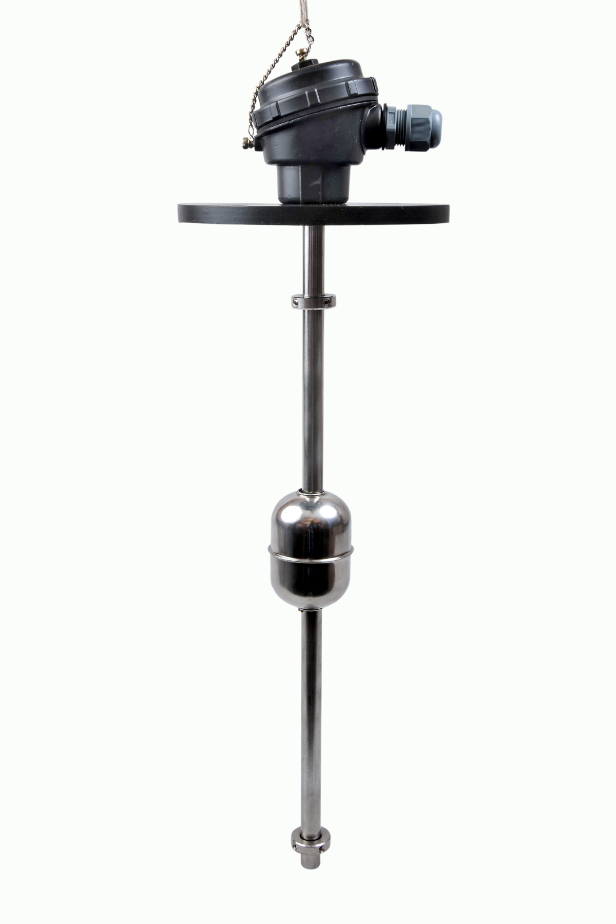 | Level Switch The Magnetic Level Switch consists of the non-abrasive float carrying permanent magnet and non-ferrous stem carrying one. View product → |
 | Level Transmitter Hydrostatic liquid level transducers and transmitters with flush diaphragm is designed fora wide variety of level measurement applications. View product → |