Start with the measurement job, not the sensor catalogue: decide whether you need continuous inventory data, a high- or low-level alarm, a local visual indication, or several of these functions together. By the end, you will be able to translate tank geometry, liquid behaviour, accuracy needs and safety requirements into a defensible sensor shortlist.
Key takeaways
- Separate continuous measurement from independent point-level overfill protection.
- Check tank geometry, nozzle access, dead zones and the full measurement range.
- Match sensing technology to liquid properties, vapour, foam, temperature and pressure.
- Specify accuracy, response time, materials, tests and failure behaviour before requesting quotes.
Define what the tank must measure and protect
Write the measurement specification before comparing instruments. Separate continuous inventory or control from point protection, then state the normal level range, required accuracy, repeatability, resolution, response time, update rate, long-term stability and safe overfill margin. A continuous transmitter is not automatically an overfill safeguard.
1. Set alarm performance against the tank process. Specify the maximum filling rate, acceptable filtering, alarm delay and shutdown time. Heavy damping can make a display look steady while delaying a high-level alarm or hiding a surge.
2. Define the process envelope: minimum and maximum temperature, pressure or vacuum, density, viscosity, foam, solids, corrosion, cleaning chemicals, nozzle size, wetted materials and hazardous-area classification. Include coating, crystallisation and the cleaning cycle.
3. If you use hydrostatic measurement, calculate density error with h = ΔP/(ρg). A 10% density change creates about 10% level error; in a 5 m water-calibrated tank, that is roughly 0.5 m of apparent error.
4. Specify the protective function separately. An independent high-high or low-low switch needs its own sensor, logic path, final element and proof-test interval; SIL describes the complete safety instrumented function, not one sensor. Record failure risks such as jammed floats, coated tuning forks and capacitance buildup.
A level sensor selection guide for industrial tanks should also state whether a stilling well or bypass is allowed. Specify its bore, venting, isolation, cleaning access and plugging tolerance, because it can introduce lag or show a level that is not representative during rapid transfer.
Check tank geometry, installation space and measurement range
Tank shape and internal equipment determine where a sensor can sit, which technology can measure reliably, and the required probe length. A vertical tank usually suits a top-mounted continuous sensor; a horizontal tank needs a position that represents the liquid volume, not simply the geometric midpoint.
A point-level switch belongs at the high, low or overfill elevation that triggers action.
For inventory, convert measured level through the tank’s calibration or strapping table. Bottom shape, dead volume, roof movement and the reference datum can create a large volume error near a dished, sloped or irregular bottom, even when the level reading appears accurate.
Check these installation points before specifying industrial tank level sensor selection:
- Measure from the proposed mounting datum to the lowest level you need to detect, then add the manufacturer’s upper and lower dead zones. This establishes the required probe length; do not order from tank height alone.
- Keep radar and ultrasonic beam paths clear of agitators, ladders, heating coils, inlet streams and tank walls. Mount away from strong reflectors, or false echoes can appear; a narrow nozzle may also restrict antenna size and beam clearance.
- Place a contacting probe where buildup, turbulence and moving roof hardware will not strike it. Leave clearance for withdrawal, cleaning and thermal expansion.
- For hydrostatic sensors, account for changing density and pressure-tap elevation. A water-calibrated transmitter can show a false level when density changes.
- Use a visual indicator only where the gauge can be seen safely and its chamber or connection matches the tank’s operating range.
Match the technology to the liquid and process conditions
A level sensor selection guide begins with the liquid’s conductivity, dielectric behaviour, viscosity, density, foam, solids and corrosiveness. These conditions determine whether industrial tank level measurement remains stable as temperature, pressure and composition change.
| Technology | Best fit | Conditions that create error or failure |
|---|---|---|
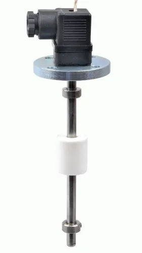
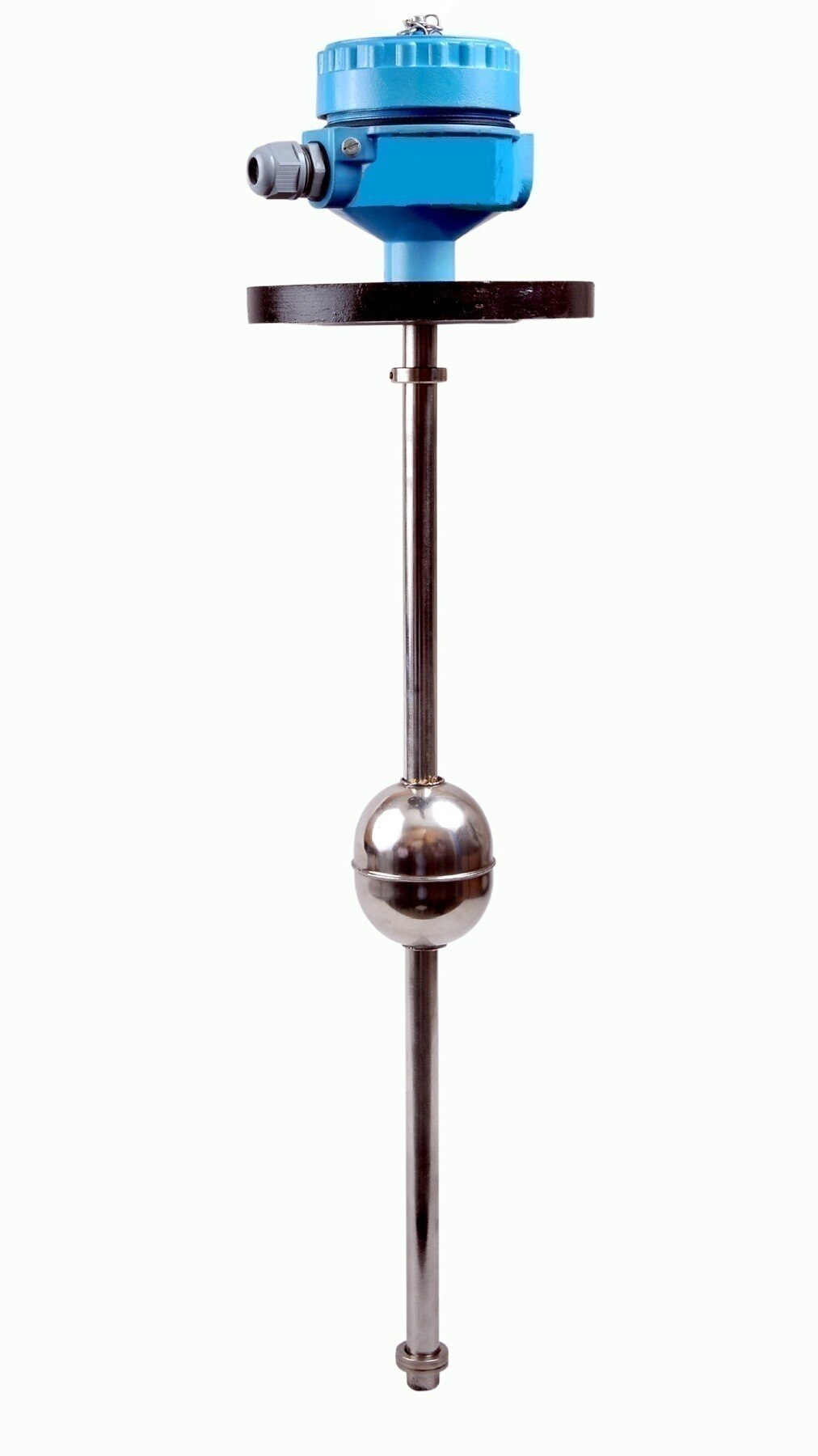
| Float | Clean, low-viscosity liquid with a stable surface; simple local or continuous indication. | Coating, crystals, turbulence or a jammed guide can stop the float moving. |
| Radar | Hot, pressurised tanks or changing vapour spaces; more tolerant than ultrasonic measurement of vapour and temperature changes. | Nozzles, ladders, coils, agitators and walls create false echoes; foam and low dielectric liquids weaken returns. |
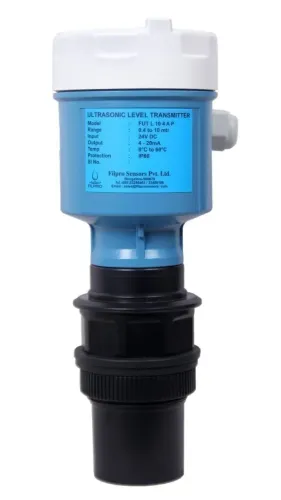
| Ultrasonic | Vented tanks with a clear gas space and moderate, stable temperature. | Foam, vapour, condensation, dust, vacuum, temperature gradients and turbulence distort sound travel. |
| Hydrostatic | Liquids with known, stable density and accessible pressure connections. | Because h = ΔP/(ρg), a 10% density change creates about a 10% level error; blending, stratification and temperature matter. |
| Capacitance | Conductive or dielectric liquids with a consistent dielectric response; suitable for point or continuous sensing. | Product buildup, changing composition, probe coating and poor grounding shift the measured capacitance. |
Specify minimum and maximum temperature, pressure or vacuum, viscosity, density, foam and solids, cleaning chemicals, wetted materials and hazardous-area classification. A continuous transmitter is not automatically an overfill safeguard: use an independent high-high switch, logic path and final element when the risk assessment requires it.
Float, tuning-fork and capacitance switches each need a failure review for jamming or coating.
Compare sensor types by strengths, failure modes and trade-offs
When choosing a level sensor for industrial tanks, compare the device against the action it must trigger: inventory control, a local reading, or an independent protective trip. A continuous level transmitter reports changing level; a point-level switch changes state at a defined limit; a visual indicator lets an operator see the level locally.
| Option | Strength | Failure modes and trade-offs |
|---|---|---|
| Continuous level transmitter | Supplies operating data for control, trending and inventory calculations; detects a rising or falling level across the tank range. | Coating, blocked probes, bad configuration, density changes and excessive damping can produce a convincing but wrong reading. Level accuracy also does not equal volume accuracy without the tank strapping table. |
| Point-level switch | Provides a simple high-high or low-low action independent of the operating measurement. Floats, tuning forks and capacitance switches suit different services. | Floats can jam; tuning forks can be affected by heavy coating or viscosity; capacitance probes can respond to buildup. Test the actual switch in its installed condition. |
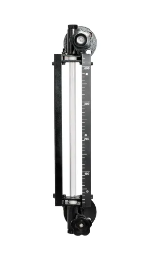
| Visual indicator | Offers an immediate local check without power, software or signal scaling. A magnetic gauge or sight glass helps verify a disputed transmitter reading. | It does not provide remote control or automatic shutdown. Fouled glass, plugged connections, closed isolation valves and poor lighting can hide the true level. |
Do not designate the continuous transmitter as the sole overfill safeguard for a high-consequence tank. Use an independent high-high sensor, logic path and final element with a defined proof-test interval; SIL describes the complete safety instrumented function, not one sensor’s accuracy.
For hydrostatic transmitters, recalculate the effect of density changes: a 10% density shift creates about a 10% inferred-level error.
Turn the shortlist into a safe, testable purchase specification
A practical level sensor selection guide for industrial tanks ends with a written, testable purchase specification. Your industrial tank sensor specification must state what the instrument will measure, what action it will trigger, and how you will prove that action before commissioning.
1. Ask for declared accuracy, repeatability, resolution, response time, update rate, damping, alarm delay, and long-term stability. Check the response against filling rate and shutdown time; excessive filtering can hide a surge.
2. Confirm maximum and minimum temperature, pressure or vacuum, density, viscosity, foam, solids, cleaning chemicals, corrosiveness, wetted materials, process connection, nozzle size, and hazardous-area classification.
3. For hydrostatic transmitters, document the density used for calibration and the error across the real density range. A 10% density shift creates about a 10% inferred-level error.
4. Treat high-high overfill protection as a separate safety function when the consequence demands it. Specify an independent sensor, logic path, final element, proof-test interval, and test method; SIL applies to the complete function, not one sensor.
5. Require wiring diagrams, calibration records, set-point tolerances, failure-state behaviour, inspection access, and acceptance-test steps. If you use a stilling well or bypass, include bore, venting, isolation, cleaning access, plugging risk, and level lag.
When evaluating Filpro Sensors Pvt Ltd, ask for these documents alongside the quoted instrument, not after installation. This turns a catalogue choice into a verifiable control and protection system.
Related products
 | Level Sensor Atex approved Float Level Transmitter : Over All Length: 300mm to 5000mm Input: 16V DC to 30V DC Output: 4-20mA / 0-10V DC Resolution: 5mm / 10mm... View product → |
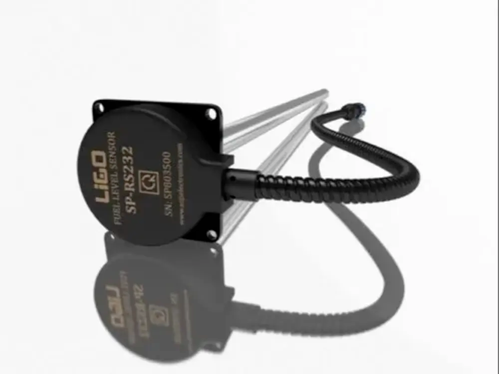 | Level Sensor Ligo fuel sensor for monitoring Diesel and Petrol level in vehicle fuel tanks and DG sets. View product → |
Frequently asked questions
What should you define before choosing an industrial tank level sensor?
Define whether you need continuous inventory or control, point protection, or both. Record the normal level range, accuracy, repeatability, resolution, response time, update rate, stability and safe overfill margin.
How do tank geometry and installation space affect sensor selection?
Check tank height, shape, nozzles, obstructions, agitators, inlet turbulence, dead zones, mounting access and the required measurement range before comparing technologies.
Which process conditions must a level sensor withstand?
Match the sensor to the liquid’s conductivity, viscosity, density, corrosiveness, foam, vapour, solids, temperature and pressure. Confirm wetted materials and hazardous-area requirements.
Why is a continuous level transmitter not automatically an overfill safeguard?
A transmitter provides measurement or control feedback, but an independent high-high level switch or protective instrumented function may be needed for overfill protection.
What belongs in a level sensor purchase specification?
State the measurement range, accuracy, response time, output, power supply, process connection, materials, environmental rating, diagnostics, failure behaviour, calibration method and factory or site acceptance tests.
Related products
 | Level Transmitter Ultrasonic Level Sensor is a non-contact ultrasonic continuous level measurement product based on sound technology. View product → |
 | Level Switch Filpro offers most reliable, cost effective Side Mounted Level Switch for point level sensing. View product → |
 | Level Transmitter Hydrostatic liquid level transducers and transmitters with flush diaphragm is designed fora wide variety of level measurement applications. View product → |
 | Level Transmitter Float Level Transmitters Are Ideal For Continuous Level Monitoring In Water, Diesel, Chemical And Oils For Accurate Level Measurement. View product → |