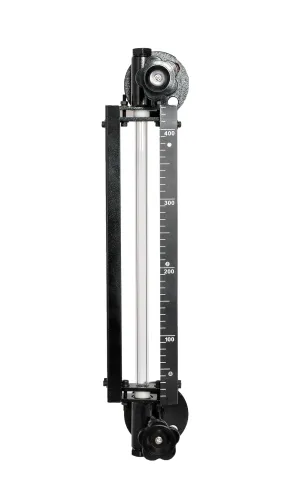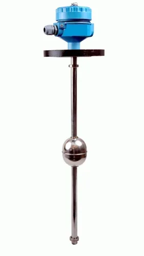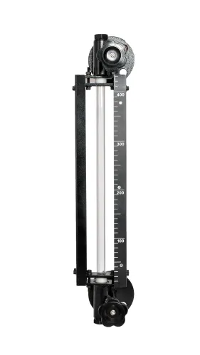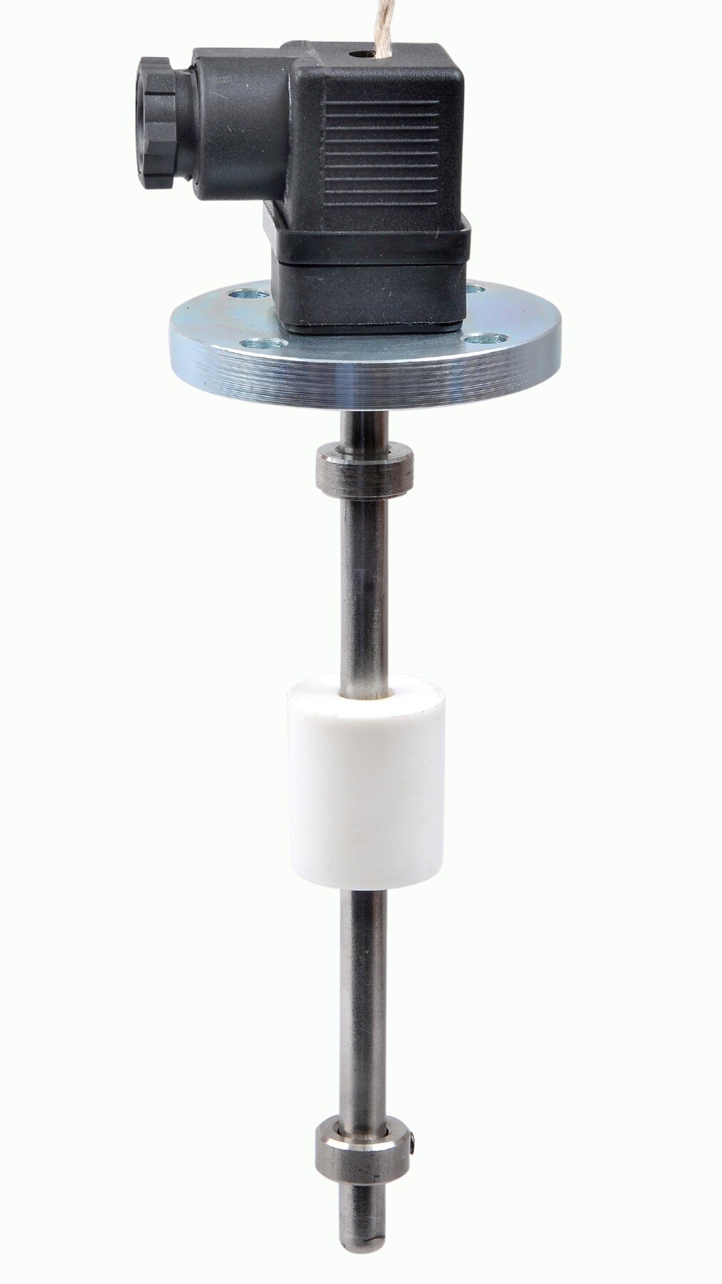
A level controller can fail because of incorrect float placement, unsafe motor wiring, a blocked impulse line, a mis-scaled 4–20 mA input or a control valve that moves in the wrong direction. By the end, you will be able to select the right sensing method, install and wire the system safely, commission each operating mode and isolate faults without adjusting calibration blindly.
Key takeaways
- Choose point-level or continuous measurement before selecting the controller.
- Wire the controller output through the pump starter, not directly to the pump motor.
- Test sensor signals, alarms and interlocks before enabling automatic operation.
- Trace faults by symptom: no signal, false switching, failed starts or failed stops.
Decide what the controller must measure and control
Before installation, decide whether you need point-level control or continuous measurement. The choice determines the sensor, controller inputs, alarms and final-control action.
| Point-level control | A float switch changes state at a fixed level | Start or stop a pump at one point |
|---|---|---|
| Continuous measurement | A 4–20 mA, 0–10 V, hydrostatic, capacitance, radar, ultrasonic or float transmitter reports level across a range | Displayed level, alarms or proportional control |
A single float switch suits a simple pump start or stop command, but it cannot show tank level. Use separate low- and high-level switches when you need independent dry-run and overflow protection. Set a switching differential between them; without enough separation, pump cycling can damage the starter and pump.
Choose fail-safe action before wiring. A filling valve must close when the controller loses power or signal if overflow is the hazard. A draining valve must close when low level threatens the process. Confirm the required action with a small manual output change before enabling automatic control.
Use this level controller setup procedure:
- Record the actual operating minimum, normal band and maximum; place low and high setpoints within those limits, not at arbitrary tank heights.
- Include the pump’s stopping margin and switching differential.
- For hydrostatic or DP measurement, enter liquid density and temperature assumptions; a 10% density change creates about 10% full-scale error without compensation.
- Test the indicated level, alarm points and valve response at known inputs.
Prepare the tank, sensing device and enclosure
Begin this level controller installation guide with a permit, electrical isolation and lockout/tagout. Isolate pumps, depressurise the vessel, drain or vent it, and prove zero pressure before opening a tank connection or removing an instrument; a zero display does not prove that a vessel is safe.
- Set the float or probe height at the actual start, stop, alarm or continuous-measurement point. Keep the sensing element vertical, provide enough cable for movement and termination, and prevent contact with walls, pipes, ladders, heating coils and other internal fittings.
- Route the cable through the correct gland, bond the enclosure and tank earths, tighten terminals, and seal unused entries. A loose gland admits moisture; poor earthing produces unstable readings.
- Shield the sensor from turbulent inflow and wave action with a stilling tube or perforated chamber. Foam, sludge and viscous liquid can foul floats; vapour can condense in sensing lines. Choose a different sensing method when a stilling arrangement cannot keep the sensor representative.
| Condition | Installation response | Failure if ignored |
|---|---|---|
| Turbulent inlet or waves | Use a stilling arrangement | Chattering output |
| Foam or sludge | Reconsider float or probe selection | False level |
| Viscous liquid | Prevent fouling or select another method | Slow or stuck response |
| Vapour or changing density | Review sensing technology and compensation | Persistent level error |
For differential pressure, remember that head equals ρgh: a 10% density change creates about 10% full-scale error without compensation. Vent the low side of an open tank to atmosphere; on a closed tank, match dry-leg or wet-leg connections.
Slope impulse lines continuously, keep process isolation valves accessible, and use the equalising valve only in the specified commissioning sequence. A partly drained or boiling wet leg causes zero shift. Filpro Sensors Pvt Ltd can help select a sensor when foam, density, temperature or mounting restrictions make the choice uncertain.
Related product
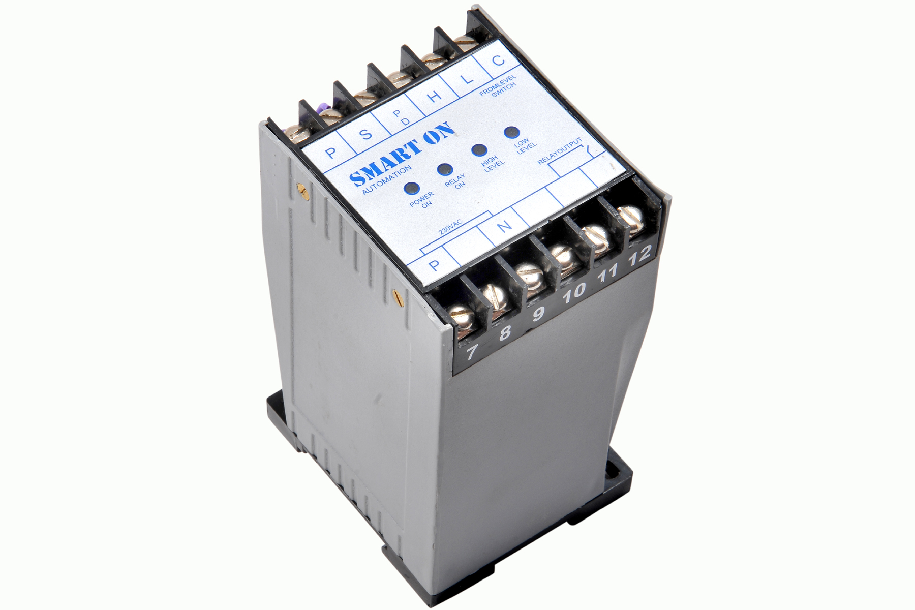 | Controller Filpro Sensors Pvt Ltd manufactures industrial Level Controller (Smart On) to automatically start & stop the pump. View product → |
Wire the controller through the pump starter
Use the control supply’s protective device to feed the level controller. The controller output then energises a contactor or motor-starter coil rated for that control voltage. The starter’s power contacts switch the pump motor, while the overload relay’s normally closed auxiliary contact returns to the control circuit so an overload drops out the coil.
A generic control chain is:
- Control supply through the required fuse or miniature circuit breaker to the controller.
- Low-level or high-level float switch in the controller’s intended enable, stop or interlock circuit. Use the normally open or normally closed arrangement shown in the wiring diagram.
- Controller output through the overload relay’s normally closed auxiliary contact to the suitably rated contactor or starter coil.
- Starter output through motor short-circuit protection and overload protection to the pump motor.
- Protective earth connected to the enclosure, starter, pump and motor cable earth conductor.
- Residual-current protection installed where the installation rules, supply arrangement or equipment instructions require it.
Do not assume the controller can switch a motor directly. Confirm the nameplate and wiring diagram for control voltage, supply voltage, single- or three-phase operation, output contact rating and direct motor-switching permission. Never bypass the overload contact or a safety interlock.
Route float and controller signal cables separately from motor and starter cables to reduce interference. Use cable glands matched to the cable diameter and enclosure rating, seal unused entries, and tighten every earth and terminal connection to the manufacturer’s specified torque.
Commission the loop before enabling automatic operation
Start commissioning with the tank empty or at a documented, known level. Record the starting condition, controller settings and alarm states before applying power or enabling automatic operation.
1. Test the low-level and high-level points. Confirm the pump starts and stops in the intended sequence, motor rotation is correct, and the pump stops before dry running. Verify that the fill cycle stops before the tank can overflow.
2. Run the pump in manual mode, then automatic mode. Confirm that each mode responds to its intended commands, that the output does not change unexpectedly during transfer, and that manual-to-automatic transfer does not create a sudden pump or valve movement.
3. For a continuous transmitter, apply several known level inputs. Check the displayed engineering units, alarm setpoints, 4–20 mA value where applicable, and configured high-signal and low-signal behaviour.
4. Command several output values and observe actual valve travel or pump response. A display-only check will miss reversed action, incorrect scaling, wrong I/O polarity and a failed valve positioner.
5. Confirm controller action with a small controlled output change. Test anti-reset-windup while the output is saturated, then verify output tracking or the defined manual-to-automatic transfer procedure. Use the level controller troubleshooting guide to classify faults in measurement, signal path, controller or final element.
6. On a DP system, establish the correct reference condition. Open isolation valves in the manufacturer’s specified sequence, use the equalizing or bypass valve correctly, and never correct a wet-leg or valve-opening problem with zero trim.
Trace level controller troubleshooting problems by symptom
Trace level controller troubleshooting problems by symptom, then separate measurement faults from signal-path, controller and final-element faults. Before touching impulse tubing or opening a vessel connection, repeat the permit, isolation, depressurisation, draining, venting and lockout/tagout controls. A zero display does not prove that the vessel is safe.
1. A flat signal points to a blocked impulse line, frozen input or saturated measurement. Check whether the process level has actually changed and compare the reading with an independent observation.
2. A noisy signal points to turbulence, foam, poor grounding or process instability. For radar or ultrasonic instruments, inspect echo quality, blocking distance and false-echo mapping; check nozzles, ladders, agitators, buildup and isolation valves that is not fully open.
3. A steady bias points to density, wet-leg, range or calibration error. Verify the configured measurement span against the actual transmitter range before adjusting the controller.
4. Cycling with changing output points to tuning, valve stiction, actuator saturation, deadband, intermittent instrument air or pump response. Compare controller output with actual valve position before changing PID gains.
For a 4–20 mA loop, measure current separately from configuration. Check open circuits, reversed polarity, loop power, loop resistance and grounded pairs; then verify scaling, damping, square-root settings, alarm interpretation and engineering units at the receiving system.
A plausible noncontact reading can still be false. Compare the displayed echo with an independent level observation before replacing the instrument, and investigate obstruction or buildup first. Test the final element separately: command several output values and confirm actual valve travel or pump response.
Frequently asked questions
How do you choose between point-level control and continuous measurement?
Use point-level control when the process needs actions at defined levels, such as start, stop, high alarm or low alarm. Use continuous measurement when you need the actual level, a trend, proportional control or multiple setpoints.
What should you check before installing a level controller?
Confirm the tank connection, sensing range, process temperature and pressure, sensor compatibility, enclosure location, cable route, earthing and access for inspection. Keep the sensing device clear of agitators, inlet turbulence, deposits and internal obstructions.
How should a level controller connect to a pump?
Connect the controller output to the pump starter or contactor control circuit, then use the starter to switch the motor. Include the overload relay, emergency stop, permissive contacts and high- or low-level interlocks required by the process.
What is the first step in level controller troubleshooting?
Classify the symptom before changing settings. Check whether the controller has power, whether the sensor signal changes with level, whether the displayed value is plausible and whether the output changes at the configured setpoint.