The wrong measurement principle, a blocked sensing path, or a missed isolation valve can produce a level signal that looks credible but is wrong. By following the selection, mechanical, wiring, configuration, and commissioning checks below, you can install a transmitter that fits the vessel and reports a defensible level.
Key takeaways
- Choose radar, hydrostatic, ultrasonic, or another principle for the tank service.
- Confirm nozzle dimensions, tank access, pressure, temperature, and hazardous-area requirements.
- Keep probes clear of inlets, agitators, tank walls, foam, and internal obstructions.
- Record the range, zero, span, wiring, calibration results, and commissioning date.
Choose the measurement principle before you order the transmitter
A tank level transmitter installation guide should choose the measurement principle before you order the instrument; mounting, process connection, calibration, and failure modes depend on that choice.
| Principle | Suits these conditions | Main limitation |
|---|---|---|
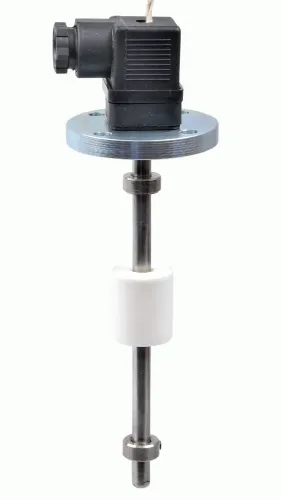
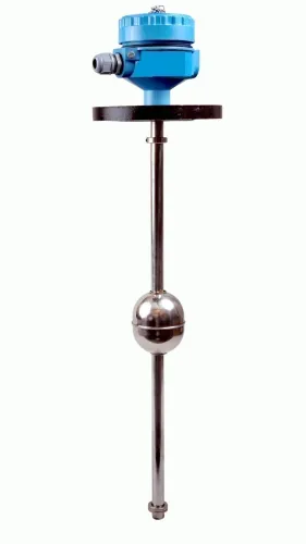
| Float | Clean liquid where guided mechanical movement is practical | Obstruction, sticking, and wall contact |
| Hydrostatic or differential-pressure | Known liquid density and a reliable pressure reference | Density changes distort level; a wet leg must stay completely filled |
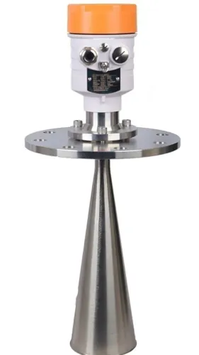
| Radar | Vapour, pressure, foam, high temperature, or conditions that compromise sound | Select the antenna and connection for the vessel service |
| Ultrasonic | Controlled temperature, vapour, foam, and turbulence with a clear acoustic return | Foam, vapour concentration, temperature gradients, and turbulence weaken the echo |
| Guided-wave radar | Narrow nozzles, internal obstructions, or changing vapour conditions | Probe clearance, coating, and mechanical loading matter |
| Displacer | Stable-density liquid and a chamber or stilling arrangement for buoyancy measurement | Density changes and mechanical friction create errors |
| Capacitance | A liquid whose conductivity and dielectric behaviour are known | Check probe insulation; buildup can change measured capacitance |
For hydrostatic measurement, use ΔP = ρgH and calibrate for the actual density range, not water by default. Before selecting the process connection or calibration range, record tank pressure, temperature, density range, foam behaviour, vapour, agitator operation, hazardous-area classification, and required accuracy. Then verify gasket, wetted materials, pressure and temperature ratings against the service.
Make the tank safe and prove that the transmitter will fit
Before you work out how to install level transmitter equipment, prove that the tank is safe and the instrument can physically fit. Do not rely on a verbal sketch or an old drawing.
1. Obtain the approved P&ID, instrument data sheet, vessel drawing, hazardous-area classification and lockout/tagout permit. Check the transmitter’s process connection, gasket, wetted materials, pressure and temperature ratings against the actual service.
2. Isolate the tank, drain or depressurise it, and purge hazardous vapour when required. Verify zero pressure before removing a blind, plug, flange or existing instrument.
3. Measure tank height, maximum and minimum liquid levels, nozzle or flange dimensions, transmitter insertion length and the clearance between the sensing element and tank bottom.
4. Inspect the vessel drawing and, where possible, the inside of the tank for heating coils, ladders, stiffeners, guide cages, agitator blades and inlet streams. Position a float so it cannot touch the wall, standpipe, coil, cage or another obstruction.
5. For radar or ultrasonic instruments, provide a clear view of the liquid surface. Keep the instrument away from wall echoes, filling streams and moving equipment, and reserve the manufacturer’s near-zone or blocking distance below the maximum level.
6. If you use a stilling well or bypass chamber, confirm open communication with the tank, openings that will not plug, and dimensions and materials suited to the selected float, probe or beam.
Do not mount until the measurements, obstruction review and hazardous-area installation requirements agree with the approved documents.
Install the process connection and sensor for the actual service
Make the mechanical installation reliable by matching the transmitter’s flange standard, nominal size, pressure class, thread size, gasket and seal materials, wetted metals, and process and ambient temperature ratings to the vessel service. A connection that threads together can still fail if the gasket swells, the diaphragm corrodes, or the pressure rating is exceeded.
Confirm hazardous-area approval before installation.
A hydrostatic transmitter measures pressure head, not level directly: ΔP = ρgH. Calculate the range using the actual liquid density and expected temperature, concentration, composition, or batch changes, then mount the diaphragm at the specified pressure reference point and orientation.
On a closed tank, connect the high-pressure side to the lower vessel tap and the low-pressure side to the vapour-space tap.
| Reference arrangement | Use it when | Failure to prevent |
|---|---|---|
| Wet leg | The reference liquid remains full and its density stays stable | Temperature change, evaporation, condensation, or freezing creates level error |
| Dry leg | Vapour cannot condense in the reference line | Condensate changes reference pressure and falsifies level |
Route impulse lines without high points in liquid-filled lines or low points in gas-filled lines. Support them independently, protect them from vibration and impact, and install suitable isolation and equalising valves. Check a float transmitter’s free travel across the entire span, including the end positions.
Filpro Sensors Pvt Ltd can help match the sensing element, seal, and connection to a difficult liquid or vessel.
Related products
 | Level Transmitter Float Level Transmitters Are Ideal For Continuous Level Monitoring In Water, Diesel, Chemical And Oils For Accurate Level Measurement. View product → |
 | Level Sensor Atex approved Float Level Transmitter : Over All Length: 300mm to 5000mm Input: 16V DC to 30V DC Output: 4-20mA / 0-10V DC Resolution: 5mm / 10mm... View product → |
Create a clear sensing path and complete the wiring correctly
Create a clear sensing path, protect the instrument from water ingress, and complete the wiring to the approved circuit design. Use this tank level transmitter installation guide:
1. Aim a radar antenna at an unobstructed liquid surface. Keep it away from tank walls, heating coils, ladders, agitators, reinforcing members, and the inlet, which can create false echoes or turbulence.
2. Protect an ultrasonic acoustic path from foam, condensation, vapour layers, temperature gradients, and turbulence. Install a properly designed stilling well when process movement prevents a stable measurement.
3. Ground the tank before installing a capacitance probe. Select an insulated probe for conductive liquid, prevent coating where possible, and calibrate with the actual liquid, not a water substitute.
4. Keep the display, terminals, diagnostic indicators, and isolation valves accessible without removing insulation or entering the tank. Point cable entries downward where practical, form a drip loop, and use the specified cable glands.
5. Separate signal wiring from power conductors and variable-frequency-drive cables. In a classified area, verify the complete protection concept: barrier or isolator, entity parameters, cable gland, conduit seal, grounding, segregation, and permitted wiring method. An approved transmitter can lose that approval when connected to incompatible associated apparatus.
6. Energise the transmitter only after checking polarity, supply voltage, shielding, and terminal tightness against the wiring diagram. Test indication at more than one known level and compare it with an independent reference.
Configure, commission, and document the level loop
A complete guide on how to install level transmitter equipment ends with proof that the loop responds correctly. Enter approved empty and full reference points, engineering units, density or specific gravity, damping, output direction, fail mode, digital protocol address, and alarm limits. Do not accept factory defaults.
- Perform a documented loop check from sensing element to transmitter, 4–20 mA or digital signal, input card, display, alarm logic, and final control element. Test both increasing and decreasing level.
- Compare the indication at more than one known level using an approved independent reference.
| Reference method | Best use | Record |
|---|---|---|
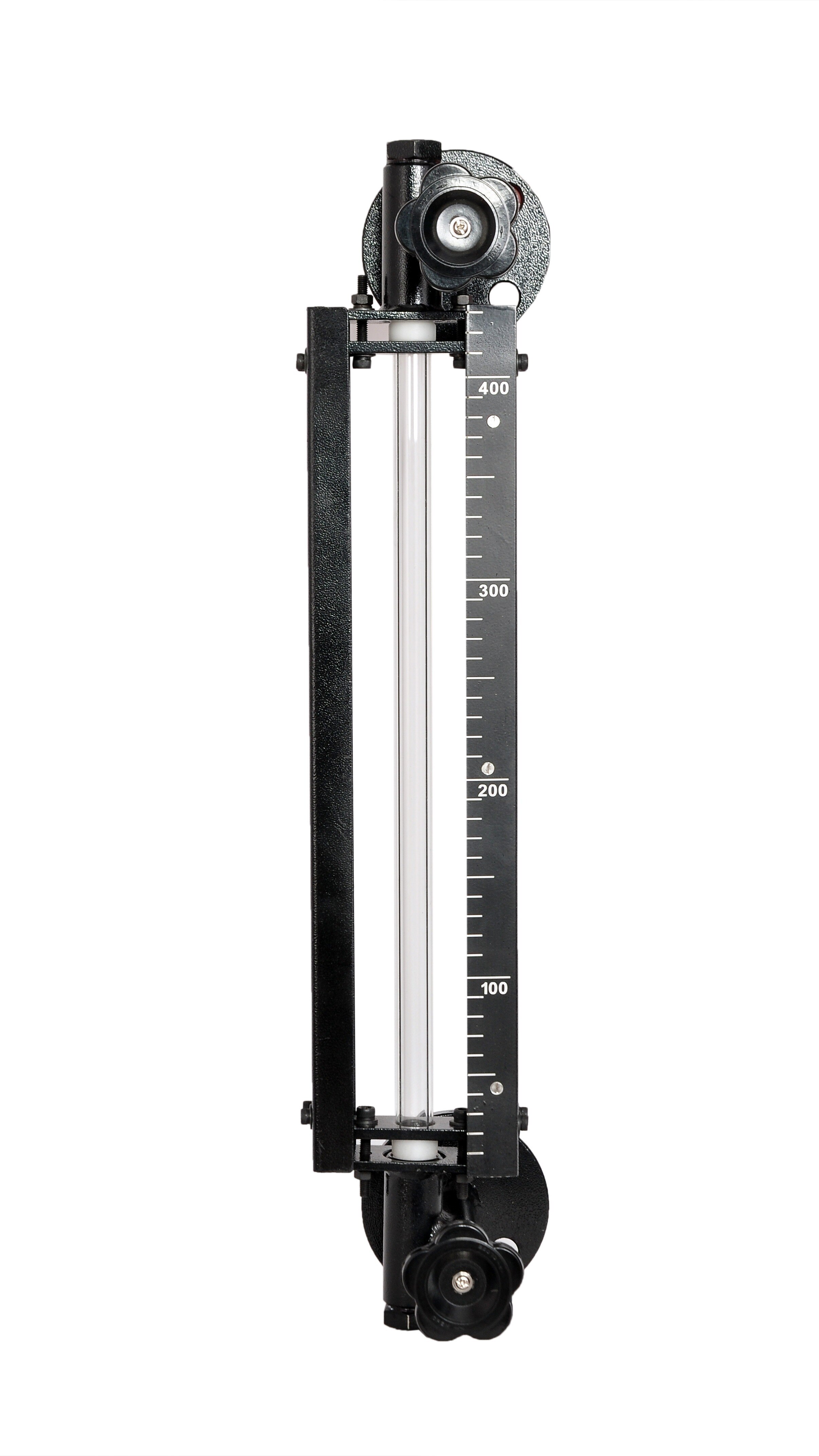
| Sight glass | Visible vessel level | Reading and temperature |
| Dip measurement | Accessible tank | Dip point and liquid condition |
| Calibrated test vessel | Controlled simulation | Applied level and result |
For hydrostatic measurement, record density and temperature at every comparison; water calibration gives a wrong result when process density changes. Check zero elevation, span, wet-leg fill, dry-leg condensate, false echoes, foam response, capacitance buildup, and float travel.
Test high and low alarms at their configured limits. Verify that an independent high-high overfill layer has separate sensor, logic solver, final element, proof-test interval, and response time; ordinary control is not that protection.
Record the as-left configuration, loop-check results, process conditions, wiring changes, calibration date, and proof-test requirements so the next technician can reproduce the installation.
Frequently asked questions
How do you choose a measurement principle for a tank level transmitter?
Match the principle to the liquid, tank geometry, pressure, temperature, vapour, foam, agitation, density changes, and required accuracy before ordering.
What must you check before installing a level transmitter?
Make the tank safe, isolate and depressurise it, verify the permit requirements, and check the nozzle, connection size, insertion length, clearance, and instrument ratings.
Where should a tank level sensor be mounted?
Choose a location with a clear sensing path and keep the sensor away from inlets, outlets, agitators, tank walls, ladders, coils, and other obstructions.
What must you document when commissioning the level loop?
Record the configured range, engineering units, zero and span, wiring terminals, calibration checks, alarm settings, test results, and final installation details.
Related products
 | Level Transmitter Hydrostatic liquid level transducers and transmitters with flush diaphragm is designed fora wide variety of level measurement applications. View product → |
 | Level Transmitter Ultrasonic Level Sensor is a non-contact ultrasonic continuous level measurement product based on sound technology. View product → |
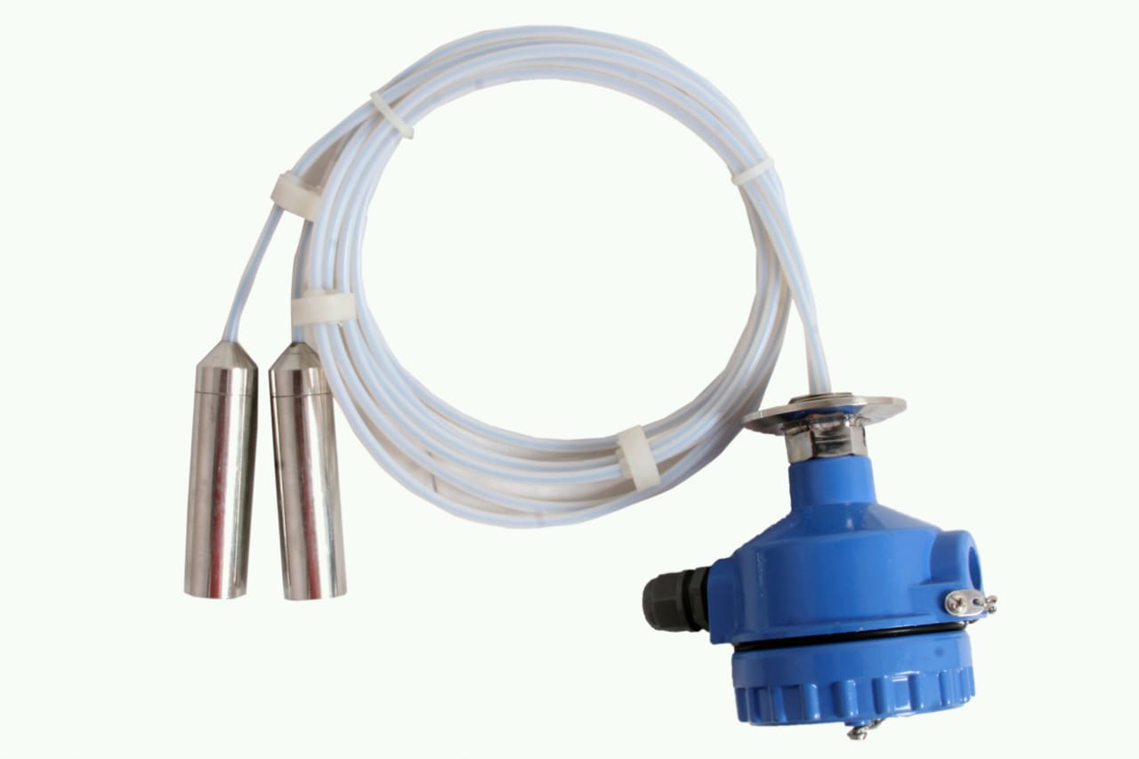 | Level Transmitter can be used for conductive as well as non conductive liquids. View product → |