A suitable accuracy target depends on tank geometry, inventory value, alarm margins and the errors added between the sensing element and the displayed value. By the end, you will be able to translate a sensor specification into millimetres and litres, judge whether a 99.5% claim is meaningful, and set a testable accuracy requirement for the installed system.
Key takeaways
- Define accuracy as ±% of span, ±% of reading, millimetres, or total error.
- Convert level error into volume using the tank’s shape and calibration table.
- Check the complete measurement chain, not only the sensor specification.
- Document reference readings, conditions, acceptance limits, and verification dates.
What does tank level sensor accuracy actually measure?
Tank level sensor accuracy measures how closely the reported level matches the actual liquid level under stated conditions. The phrase tank level sensor accuracy is incomplete without its basis: ±0.1% of span, ±0.1% of reading, a millimetre value, or total measured error. Check whether it applies to the sensing element, transmitter output, or complete indicator.
- Resolution is the smallest displayed or detected increment. A sensor resolving 5 mm can still report a level 20 mm above the true level.
- Repeatability is how closely the sensor returns to the same value when the same level is measured repeatedly. Consistent error is still error.
- Hysteresis is the difference in output at one level when the liquid is rising versus falling.
- Linearity describes how closely readings follow the ideal level-to-output relationship across the measuring span. It is not the same as total error.
- Drift is a change in the reading over time, temperature, supply voltage, or electronics ageing.
- Response time is how quickly the output follows a level change. It says nothing about whether the final value is accurate.
For example, ±0.1% of a 10 m span means about ±10 mm across the range, including at a 1 m level; it does not mean ±1 mm there. Confirm the reference temperature, mounting, ambient conditions, supply voltage, measuring range, and stability period.
Tank geometry, pressure effects, damping, noise, latency, and update rate can create larger practical errors than the headline figure.
How do you turn an accuracy specification into a usable tolerance?
Turn tank level sensor accuracy into a usable tolerance by converting every specification into millimetres at the levels that matter, then comparing that result with your process limit.
| Option | What it means | Example on a 0–10 m range |
|---|---|---|
| ±millimetres | Fixed absolute error across the stated range | ±5 mm remains ±5 mm at 1 m and 9 m |
| ±percentage of full scale (span) | Error is based on configured measuring span | ±0.1% of 10 m = ±10 mm everywhere |
| ±percentage of reading | Error rises with measured level | ±0.5% at 2 m = ±10 mm; at 8 m = ±40 mm |
| Combined error | Adds separate span and reading terms | ±(0.1% span + 0.05% reading) at 2 m = ±11 mm |
Percentage of span is common. Do not mistake ±0.1% of a 10 m span for ±0.1% at each measured level; it is approximately ±10 mm even when the liquid is only 1 m high.
Choose a range that covers operating and alarm levels without excessive unused span. Configuring a 0–10 m transmitter for a process using 0–4 m doubles the span-based error compared with a 0–5 m range.
Ask whether the figure covers linearity alone or total measured error, and whether it applies to the sensing element, transmitter output, or complete loop. The display, input card, scaling and resolution can add error, so test the displayed value when that is what controls an alarm or inventory decision.
Radar’s millimetre figure does not remove false echoes from ladders, nozzles or agitators. Compare the resulting tolerance with your overfill margin and minimum usable inventory.
How does a millimetre error become a volume error?
A 10 mm level error does not represent the same inventory error in every tank. In a vertical cylinder, the error is constant at every level; in a horizontal cylinder, it changes with the liquid height.
| Tank type | Volume error from a small level error | Example |
|---|---|---|
| Vertical cylinder | π × D² ÷ 4 litres per millimetre | A 3 m diameter tank: 7.07 L/mm, or 70.7 L for 10 mm |
| Horizontal cylinder | L × 2 × square root of [r² − (h − r)²] litres per millimetre | A 3 m diameter, 10 m long tank at half-full: 30 L/mm, or 300 L for 10 mm |
In the table, D is tank diameter, r is radius, L is tank length, and h is liquid height measured from the bottom. The horizontal-tank result is largest around the middle of the shell, where a small rise covers the widest part of the cylinder.
Near the bottom or top, the same level change represents less volume.
Use the exact segment-volume calculation when the error is large relative to the tank diameter or the level is close to an end. A 10 mm error in a wide horizontal tank can therefore exceed the inventory error from the same sensor in a much taller vertical tank.
These calculations describe geometry, not the complete measurement system. An outdated strapping table, internal coils or a false echo can add a separate error that a millimetre-rated sensor cannot remove.
Why can the displayed level be less accurate than the sensor?
The displayed value can be less accurate than the sensing element because tank level indicator accuracy belongs to the entire measurement loop. Transmitter conversion, cable resistance or interference, PLC input-card accuracy, analogue-to-digital conversion, display scaling and indicator resolution can each shift the value an operator sees.
- The transmitter can add calibration error, temperature drift, static-pressure effects and long-term drift.
- The cable can introduce noise, voltage drop or a poor shield connection, especially on long analogue runs.
- The PLC input can have its own gain, offset and conversion error.
- Incorrect display scaling can turn a correct 4–20 mA signal into the wrong tank height.
- Display rounding can hide small changes even when the transmitted signal is correct.
- Installation conditions such as turbulence, foam, vapour, condensation, unsuitable mounting or a changing reference point can make the measured level differ from the actual level.
A claim such as “99.5% accuracy” is incomplete. Ask whether it means ±0.5% of span or reading, whether it covers linearity or total measured error, and whether it applies to the sensor, transmitter output or complete indicator. Ask for the temperature range, calibration conditions and stability period too.
For independent transmitter, PLC and display errors, adding worst-case limits is conservative; a root-sum-square estimate is less conservative. The supplier must state which method was used. Test the complete loop, not only the sensor, when the displayed level drives alarms or control.
Deadband, damping, update rate and latency can still make a highly accurate signal perform poorly in feedback control.
How should you set, verify and document the required accuracy?
Set the target from the consequence of error, then specify tank level sensor accuracy for the complete installed loop. Inventory needs an error small enough to protect the minimum usable stock and reorder point; overfill protection needs margin below the high-high alarm; control needs stable feedback, not just a small static error.
| Driver | Choose the target by | Verify during selection |
|---|---|---|
| Inventory | Convert level error through the tank strapping table and compare it with the minimum usable volume and reorder threshold | Use the current, calibrated level-to-volume table |
| Alarm | Keep worst-case measurement error below the gap between the alarm setpoint and the safe operating limit | Test at alarm points, including signal and display errors |
| Control | Match accuracy with deadband, damping, update rate, latency and process noise | Confirm stable response at the controller’s actual scan and tuning settings |
Specify the sensor range around the real operating and alarm levels. A 0–10 m range used for a 0–4 m process doubles the absolute error of a 0.1% of span specification compared with a 0–5 m range.
State whether accuracy is ±millimetres, percent of span or percent of reading; include linearity or total error, reference temperature, operating temperature, stability period and the point in the loop where it applies.
- Test the sensor, transmitter, wiring, input card and display as one loop at low, mid and high levels.
- Record applied level, output signal, displayed value, alarm state and control response.
- File calibration certificates, range settings, strapping-table revision and acceptance limits.
Ask Filpro Sensors Pvt Ltd to quote tank level indicator accuracy at the display or control-system input, not only the sensing element.
Related products
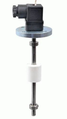
 | Level Sensor Atex approved Float Level Transmitter : Over All Length: 300mm to 5000mm Input: 16V DC to 30V DC Output: 4-20mA / 0-10V DC Resolution: 5mm / 10mm... View product → |
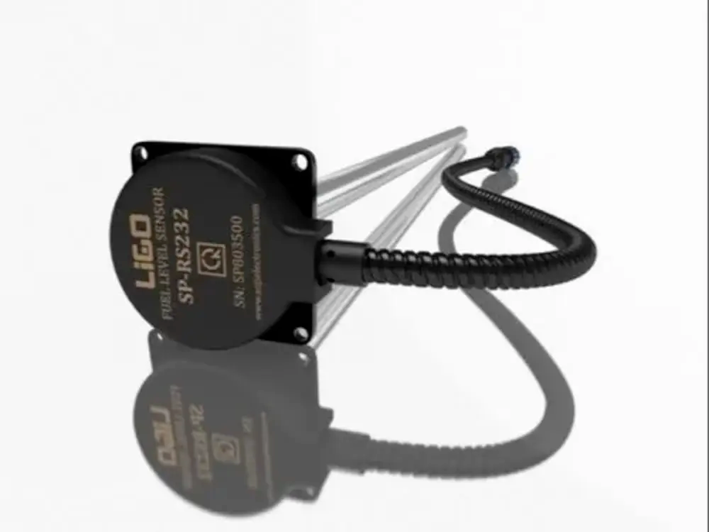 | Level Sensor Ligo fuel sensor for monitoring Diesel and Petrol level in vehicle fuel tanks and DG sets. View product → |
Frequently asked questions
What does tank level sensor accuracy actually measure?
It measures how closely the reported level matches the actual liquid level under stated conditions. Check whether the specification applies to the sensing element, transmitter output, or complete indicator, and identify whether it uses ±% of span, ±% of reading, millimetres, or total measured error.
How do you turn an accuracy specification into a usable tolerance?
First identify the specification basis. For example, ±0.1% of a 2,000 mm span equals ±2 mm across the range, while ±0.1% of reading changes with the measured level. Add stated effects such as temperature, supply variation, installation conditions, and repeatability when defining the total tolerance.
How does a millimetre error become a volume error?
Use the tank’s cross-sectional area at the measured level. In a uniform cylindrical tank, volume error equals area multiplied by height error. Horizontal, conical, dished, and irregular tanks need a calibration table or volume-versus-level calculation because the same millimetre error represents different volumes at different heights.
Why can the displayed level be less accurate than the sensor?
The complete reading can include transmitter resolution, display rounding, analogue-loop error, cable effects, calibration error, installation position, temperature, turbulence, foam, vapour, and tank geometry. Evaluate the full chain from liquid surface to displayed value.
How should you set, verify and document the required accuracy?
Define the process decision first, then set an allowable level or volume error. Record the sensor range, accuracy basis, reference instrument, test levels, liquid and temperature, installation conditions, readings, acceptance limits, adjustment made, and verification date.
Related products
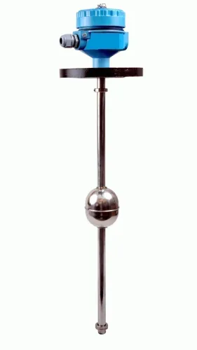
 | Level Transmitter Float Level Transmitters Are Ideal For Continuous Level Monitoring In Water, Diesel, Chemical And Oils For Accurate Level Measurement. View product → |
 | Level Transmitter Hydrostatic liquid level transducers and transmitters with flush diaphragm is designed fora wide variety of level measurement applications. View product → |
 | Level Transmitter Ultrasonic Level Sensor is a non-contact ultrasonic continuous level measurement product based on sound technology. View product → |
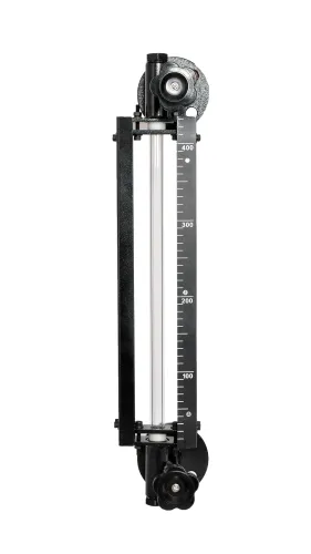
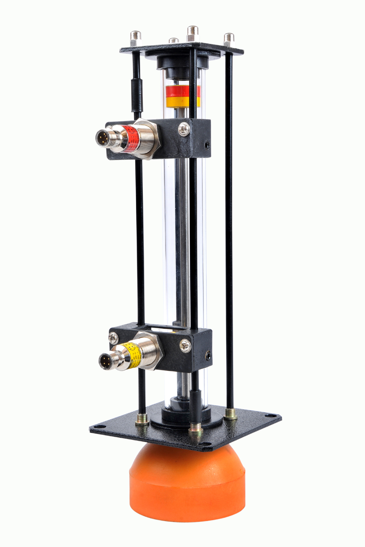 | Level Gauge Oil Level Indicator is designed to indicate the coolant and hydraulic oil level inside the tank with a visual indicator above the tank. View product → |