Choosing an output is an integration decision, not just a transmitter specification. By matching the signal to your PLC, SCADA system, vehicle controller, cable route and fault-detection needs, you can avoid incompatible inputs, unstable readings and unnecessary wiring changes.
Key takeaways
- Choose 4–20 mA for long cables, noise resistance, and dependable single-value measurement.
- Use digital outputs when you need diagnostics, multiple variables, or configuration data.
- Confirm the transmitter signal matches the receiver input, wiring, and power supply.
- Scale the output against the tank’s actual empty and full measurement points.
Choose 4–20 mA when reliability and cable distance matter
Choose 4–20 mA when reliability and cable distance matter: it is the default for many industrial level measurements. A 4–20 mA level transmitter uses two-wire loop wiring, and the receiver measures the same current despite cable voltage drop. The loop also resists electrical noise better than a voltage signal.
4 mA represents the configured empty point and 20 mA the full point, so a valid zero is distinct from an open circuit or lost loop current.
| Signal option | Main advantage | Check before choosing |
|---|---|---|
| 4–20 mA | Noise-resistant, two-wire wiring, long cable runs | Configure the input for loop current and fault diagnostics |
| 0–10 V | Convenient for nearby PLCs, displays or data loggers | Check grounding, common-mode voltage, cable length and input impedance |
| 0–5 V | Useful for equipment designed around a lower voltage span | Confirm the input range and scaling exactly |
NAMUR NE 43 installations commonly treat 3.8–20.5 mA as the normal measurement range; ≤3.6 mA or ≥21.0 mA indicates a fault band. The receiving input must be configured to interpret these bands; a 4–20 mA input does not add NE 43 diagnostics automatically.
Choose 0–10 V or 0–5 V only when the input card, data logger, display or vehicle controller matches it. Do not select a voltage output by habit: grounding errors, common-mode voltage and cable voltage drop can corrupt the reading.
These checks make the level transmitter output signal options fit the installation rather than just the instrument label.
Use digital outputs when you need data beyond one level value
Choose digital outputs when your control system needs status, diagnostics, configuration, or secondary variables—not just one level value. Among level transmitter output signal types and level transmitter output signal options, RS-485 suits a network because it uses differential digital signalling, device addressing, and multidrop wiring.
RS-485 is not a complete protocol. An RS-485 level transmitter requires confirmed Modbus RTU settings, register mapping, baud rate, parity, stop bits, termination, biasing, and diagnostic codes.
RS-232 is point-to-point, with shorter practical cable runs and greater sensitivity to industrial interference. Use it for one nearby device, not a properly terminated multidrop network.
A HART level transmitter superimposes digital communication on a conventional 4–20 mA loop. The analogue level remains available while configuration, status, secondary variables, and diagnostics travel digitally.
Before specifying a digital output, check:
- The PLC or DCS supports the protocol and can map scaling, status, and diagnostic data.
- HART loop resistance, input isolation, and receiver filtering meet the transmitter’s requirements.
- FOUNDATION Fieldbus H1 or PROFIBUS PA installation plans include terminators, spurs, host tools, segment power, and device-count limits.
FOUNDATION Fieldbus H1 and PROFIBUS PA use shared, bus-powered 31.25 kbit/s segments; they are not interchangeable with each other or with RS-485. Choose between them according to the installed host and asset-management system.
IO-Link, WirelessHART, ISA100.11a, and Ethernet-APL require compatible masters, gateways, switches, or networks.
Match the signal to the wiring and receiving hardware
Match level transmitter output signal options to the wiring and receiving hardware before you order. A two-wire 4–20 mA transmitter gets power through the loop; a three-wire voltage transmitter needs separate DC power, signal wiring and a defined common ground. Reverse polarity can produce no reading or damage equipment.
Ground the shield at one end according to the plant’s EMC practice; do not bond it at both ends by default.
1. For 4–20 mA wiring, calculate available loop voltage against the transmitter’s minimum supply voltage, PLC or indicator input burden, and cable resistance. Do not assume any cable length will work. Confirm the PLC analogue input, SCADA card, indicator, vehicle ECU or gateway accepts 4–20 mA.
2. For a 0–5 V level transmitter or 0–10 V output, check receiving input impedance, reference ground, cable voltage drop and common-mode limits. A voltage input can show a wrong level when its ground shifts or the cable loses voltage. Confirm the receiver accepts the exact range.
3. For RS-485 wiring, use a twisted pair with consistent polarity, one bus topology, end termination and correctly configured biasing. Terminate the two bus ends, not every spur. Confirm the protocol, such as Modbus RTU, register map and serial settings. Use RS-232 for a direct point-to-point connection.
A signal converter is an engineering change, not a guaranteed fix: it adds power, scaling, isolation and failure points that must be specified and tested.
Scale the output so the control system reports the real level
Level transmitter scaling converts a signal into the tank level your control system displays. Define the empty and full points physically, such as the probe’s installed lower and upper calibration points; do not assume they equal 0% and 100% of tank capacity.
For a linear 4–20 mA transmitter:
level = empty level + ((measured mA − 4) ÷ 16) × span
For 0–10 V level scaling, replace 4 with 0 and 16 with 10. For 0–5 V, replace them with 0 and 5. The result can be millimetres, percent, litres or cubic metres. If the signal falls as the tank fills, reverse the calculation so the control system reports increasing level in the correct direction.
Non-linear tanks require a volume table or geometry calculation; a cylindrical tank lying horizontally does not produce volume proportional to height.
- Record the transmitter’s lower range value, upper range value, engineering unit and configured direction.
- Apply empty, a known intermediate level and full reference points, then compare each displayed value with the physical measurement.
- Record the PLC input scaling, transmitter range and final correction.
For RS-485, identify the protocol, register, data type, scale factor, byte order and status bits. For HART, identify the primary process variable while retaining the analogue value; HART adds digital diagnostics to the 4–20 mA loop. For fieldbus, identify the process-value object and status code.
Configure under-range, overrange and fault states separately; do not convert every abnormal signal into a plausible level. Examine NE 43 bands such as ≤3.6 mA and ≥21.0 mA when used.
Make the final choice from the whole measurement system
Make the final choice from the complete measurement system, not from the transmitter alone. These level transmitter output signal types suit different receiving equipment, wiring layouts and maintenance practices.
| Signal | Choose it when | Watch for |
|---|---|---|
| 4–20 mA | You need a robust point-to-point signal over a long cable route | Check loop power, resistance and the 4 mA live-zero fault interpretation |
| 0–5 V or 0–10 V | The nearby PLC, logger or controller explicitly requires that range | Confirm the shared reference and protect against voltage drop and ground differences |
| RS-485 with Modbus RTU | One network must carry addressed values, status and diagnostics | Set addresses, serial parameters, termination, biasing and register mapping |
| HART | You want digital configuration and diagnostics while retaining the normal analogue loop | Confirm the host supports HART communication |
| PROFIBUS PA or FOUNDATION Fieldbus H1 | The installed host, powered segment and maintenance tools already support the bus | Check segment power, terminators, spurs, device count and interoperability |
| Relay or pulse/frequency | The receiver needs an alarm contact or counting input | Specify trip behaviour, or scaling, frequency limits and fault response |
Use this level transmitter selection checklist before placing an order:
- Give Filpro Sensors Pvt Ltd the input type, supply voltage, cable length, protocol and required level range so the complete loop can be checked.
- Treat wireless and Ethernet-APL as network designs: confirm gateways, update rates, capacity and loss-of-communication behaviour.
- Do not treat any output as safety-rated by itself; a safety instrumented function needs suitable certification, diagnostics, proof testing, logic solving and final-element design.
Related products
 | Level Transmitter Float Level Transmitters Are Ideal For Continuous Level Monitoring In Water, Diesel, Chemical And Oils For Accurate Level Measurement. View product → |
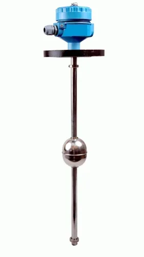
 | Level Sensor Atex approved Float Level Transmitter : Over All Length: 300mm to 5000mm Input: 16V DC to 30V DC Output: 4-20mA / 0-10V DC Resolution: 5mm / 10mm... View product → |
Frequently asked questions
Why choose a 4–20 mA output for a level transmitter?
Choose 4–20 mA when reliability, long cable runs, and resistance to electrical noise matter. The receiver measures loop current despite cable voltage drop.
When should you use a digital level transmitter output?
Use a digital output when you need data beyond one level value, such as diagnostics, configuration information, or additional process variables.
How do you match a level transmitter output to control-system hardware?
Check that the transmitter signal type matches the receiver input, wiring arrangement, power supply, and communication requirements before installation.
Why does output scaling matter for level measurement?
Correct scaling makes the control system report the real tank level by linking the transmitter’s output range to the actual empty and full measurement points.
Related products
 | Level Transmitter Ultrasonic Level Sensor is a non-contact ultrasonic continuous level measurement product based on sound technology. View product → |
 | Level Transmitter Hydrostatic liquid level transducers and transmitters with flush diaphragm is designed fora wide variety of level measurement applications. View product → |
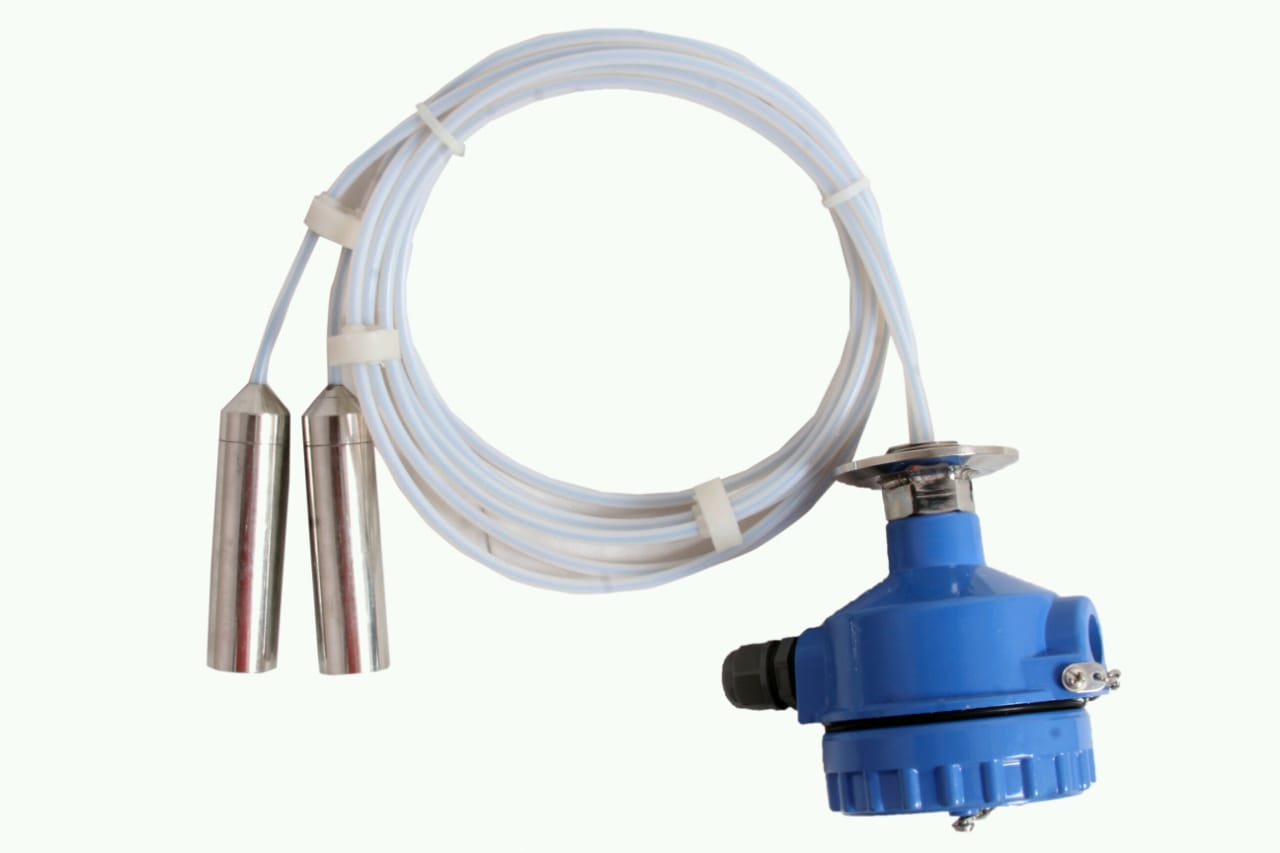 | Level Transmitter can be used for conductive as well as non conductive liquids. View product → |
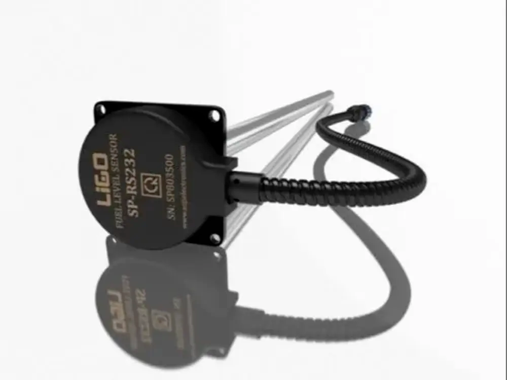 | Level Sensor Ligo fuel sensor for monitoring Diesel and Petrol level in vehicle fuel tanks and DG sets. View product → |