Start with the tank’s maximum and minimum gauge pressure, absolute pressure, vacuum condition, design temperature and fluid chemistry—not with the connection size. By the end, you will be able to compare visual gauges, magnetic indicators, hydrostatic instruments, radar and guided-wave radar against the complete pressure boundary and reject specifications that rate only one component.
Key takeaways
- Record design and operating pressure, temperature, fluid and vessel details.
- Match gauge technology to fluid properties, tank geometry and required visibility.
- Verify the complete pressure boundary, flange rating and gasket compatibility.
- Demand material certificates, pressure tests and documented supplier review.
What pressure and temperature data must you collect before selecting a gauge?
Before selecting a level gauge for high pressure tanks, collect the vessel’s operating conditions and design limits. High-pressure service is defined by the pressure–temperature duty on the complete pressure boundary, not by tank pressure or connection size alone.
- Record normal, minimum and maximum operating pressure in gauge and absolute terms, plus vacuum, relief-valve set pressure, surges and blocked-in conditions.
- Record design pressure, full-vacuum or external-pressure requirement, and design and operating temperatures during startup, shutdown, steam-out and upset conditions.
- Provide liquid specific gravity across its temperature and composition range. This determines the accuracy of hydrostatic and differential-pressure readings.
- Give nozzle elevations, required level range, connection size and facing, and whether the chamber can be isolated and thermally blocked in.
- Request allowable working pressure at the specified temperature, not hydrostatic test pressure. Obtain the test standard and material and inspection records for pressure-retaining parts.
| Instrument approach | Pressure-temperature information to compare | Additional condition |
|---|---|---|
| Visual glass or magnetic bypass | Rate the body, glass or float chamber, flanges, gaskets, bolting and end connections at maximum temperature; the lowest rating governs. ASME B16.34 tables cover valves, not automatically the assembly. | Confirm upper and lower isolation, drain or vent capability and release protection. Review thermal relief for blocked-in liquid; automatic ball-check protection does not replace the pressure rating. |
| Differential pressure | Define pressure range, temperature range and liquid-density range. | Specify wet-leg, dry-leg, condensate or remote-seal conditions so calibration reflects the installation. |
| Radar or guided-wave radar | Check the antenna or probe, seals and process connection against pressure, temperature and vacuum. | Confirm compatibility with vapour, foam and dielectric changes. |
Which level technology fits the liquid, vessel and visibility requirement?
Choose the measurement principle that matches the liquid’s behaviour, the vessel geometry and what operators must see. A level gauge for high pressure tanks must also be rated as a complete pressure boundary, because the lowest-rated glass, chamber, valve, gasket, bolting or connection governs the safe limit.
| Option | What it means | When it applies |
|---|---|---|
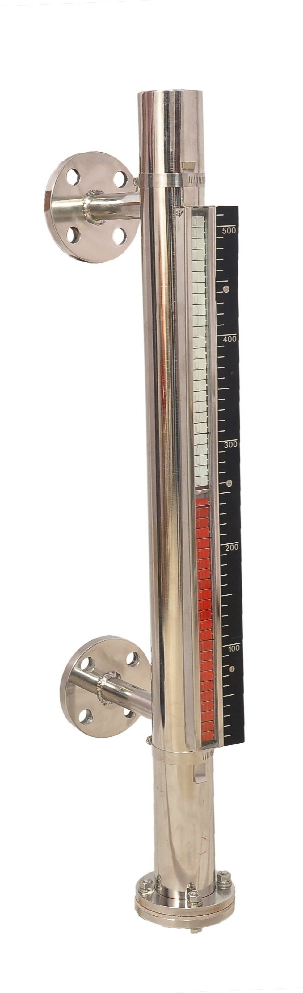
| Magnetic level indicator | A float drives an external magnetic flag or capsule display | Choose for continuous local indication when the liquid is opaque and a sealed visual chamber is acceptable. Size and locate connections to represent the actual tank range; review thermal relief for blocked-in chamber liquid. |
| Reflex glass gauge | Prismatic glass shows liquid dark and vapour light | Choose for simple point-to-point indication when colour, emulsions and thin interfaces do not matter. |
| Transparent glass gauge | Clear glass exposes the liquid directly | Choose to observe colour, multiple interfaces or a thin boundary. Confirm visibility and protection against breakage. |
| Hydrostatic or differential-pressure instrument | Infers level from pressure or pressure difference | Choose when no internal probe is wanted, but account for density changes, impulse-line plugging and vapour-space pressure. |
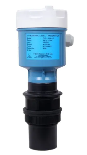
| Radar | Measures level without touching the liquid | Choose for hot, toxic, corrosive or inaccessible service; foam, condensation, vapour, agitators and low dielectric constant can weaken echoes. |
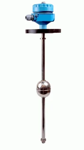
| Guided-wave radar | Sends a signal along an immersed probe | Choose for narrow nozzles or some low-dielectric liquids. Check probe buckling, coating, anchoring and internal clearance. |
| Displacer | Measures buoyancy rather than height directly | Choose when density is stable; density, composition or second-phase changes create level error. |
For radar, rate the antenna, nozzle and process seal. For guided-wave radar, the probe becomes part of the pressure boundary, and a rigid probe is not interchangeable with a cable probe.
How do you verify the complete pressure boundary and flange connection?
For a level gauge for high pressure tanks, verify the pressure–temperature rating of the complete pressure boundary, not the vessel pressure or connection size alone. The lowest-rated component governs safe operation.
1. Request the gauge’s allowable maximum working pressure at the maximum design temperature. Compare it with the tank’s design pressure, not only its normal operating pressure. Record hydrostatic test pressure separately: it is a temporary qualification or inspection value, not an operating limit.
2. Check temperature derating for the gauge body, float chamber, glass, process valves, gaskets, seals, bolting and end connections. Ask for material and inspection records for every pressure-retaining part.
3. Confirm the full vacuum rating or external-pressure limit. A chamber rated for internal pressure can collapse under vacuum if it lacks an adequate vacuum design.
4. Match the isolation valves to the pressure and temperature using the applicable pressure–temperature table. ASME B16.34 applies to valves and valve bodies; it does not automatically rate the assembled gauge. Specify upper and lower isolation, drain or vent capability, and thermal relief for blocked-in liquid.
5. Examine glass type, thickness and protection against impact. Add automatic ball-check or excess-flow protection when a glass failure could rapidly release liquid, but do not treat it as a substitute for pressure rating or operating controls.
6. Verify gasket material, bolt grade and tightening requirements, then identify the flange standard and class, such as ASME B16.5 or ASME B16.47. Do not accept “Class 300” or a nominal bore without its temperature-specific rating and facing details.
For a bypass magnetic gauge, confirm that connection locations represent the actual level range. A pressure-rated chamber alone proves nothing.
Will the selected gauge survive the fluid and the pressure-system hazards?
A level gauge for high pressure tanks survives only when its complete pressure boundary matches the fluid, pressure and temperature, and its release path is controlled. Check the body, glass or float chamber, seals, welds, bolting, gaskets, end connections and isolation valves at maximum design temperature. The lowest pressure–temperature rating governs.
ASME B16.34 tables cover valve bodies, not automatically the assembled gauge.
1. Match every wetted material to the service. Steam demands resistance to temperature and thermal shock; hydrocarbons demand leak and ignition control; toxic fluids demand containment. Sour service requires hydrogen-sulfide qualification, while chloride-bearing fluids require review for chloride stress-corrosion cracking. Cryogenic service needs materials and seals that remain ductile at low temperature.
Flashing liquids need erosion and two-phase-flow review. Solids-bearing liquids need protection against plugging, abrasion and inaccurate readings. “Stainless steel” alone is not a specification.
2. Specify upper and lower isolation valves, a chamber depressurization and drain or vent path, and safeguards against uncontrolled release. Automatic ball-check or excess-flow protection can limit discharge after glass failure, but cannot replace pressure rating or operating procedures.
3. For a bypass magnetic gauge, size and locate connections to represent the tank’s actual level range. Review thermal relief for liquid trapped in a blocked-in chamber.
Radar avoids direct exposure in hot, toxic or corrosive service, but its nozzle, antenna seal and process connection still need rating. Foam, condensation, heavy vapour, agitators and low-dielectric liquids can degrade the echo.
What should a purchase specification and supplier review contain?
Approve a level gauge for high pressure tanks only after the supplier proves the complete pressure boundary at the specified temperature. Hydrostatic test pressure is a temporary qualification condition, not permission to operate at that pressure; the lowest-rated glass, chamber, valve, flange, gasket, bolting or connection sets the allowable limit.
Request these items before approval:
- A signed datasheet stating allowable working pressure at maximum and minimum design temperatures, vacuum rating, test pressure, test standard and pressure class for the complete assembly.
- A pressure-boundary material schedule, including certificates and inspection records for the chamber, glass, valves, flanges, bolting and gaskets.
- General-arrangement and connection drawings showing upper and lower elevations, level range, isolation valves, vent and drain points, relief protection and any automatic ball-check or excess-flow device.
- Design calculations covering pressure, temperature, flange loading, glass or chamber stress, thermal expansion and blocked-in liquid relief.
- For differential-pressure transmitters, the calibration basis and impulse-line drawing, identifying wet-leg, dry-leg, condensate and remote-seal conditions.
Review the drawing against the vessel nozzle locations and confirm that ASME B16.34 data applies only to the valve, not automatically to the assembled gauge. Filpro Sensors Pvt Ltd can help close gaps by checking the selected instrument against the service envelope, documenting connection details and identifying missing pressure-boundary or inspection evidence before manufacture.
Related products
 | Level Transmitter Hydrostatic liquid level transducers and transmitters with flush diaphragm is designed fora wide variety of level measurement applications. View product → |
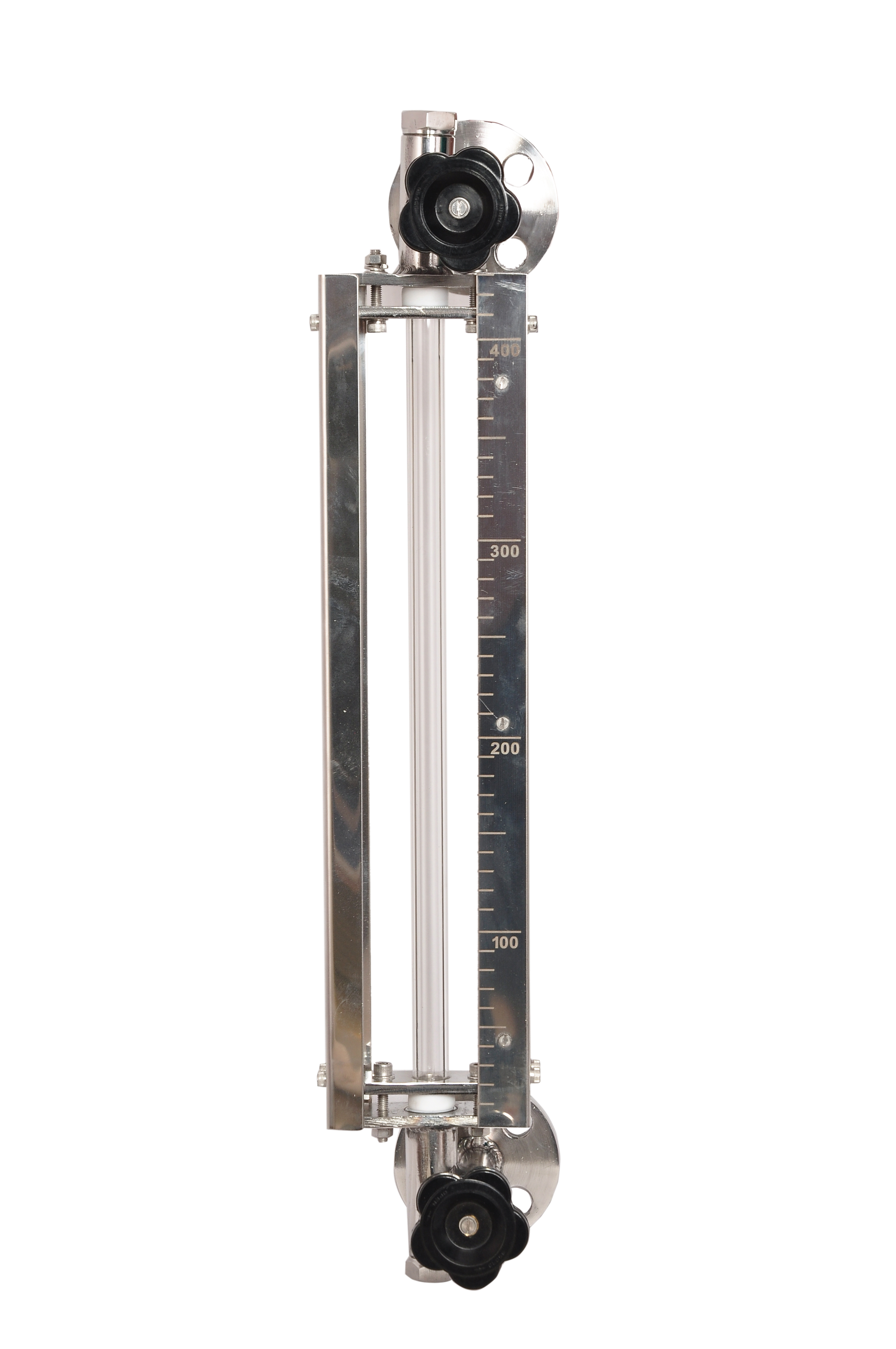 | Level Gauge Tubular Glass Level Indicator is used for visual level indication of liquid in storage and process tanks. View product → |
Frequently asked questions
What pressure and temperature data must you collect before selecting a gauge?
Collect design and operating pressure, design and operating temperature, pressure cycles, vacuum conditions, fluid properties, vessel material, connection size and flange rating.
Which level technology fits a high-pressure tank?
Choose between reflex or transparent glass, magnetic level gauges, displacers and transmitters by comparing fluid clarity, temperature, pressure, visibility, accuracy and maintenance access.
How do you verify the pressure boundary and flange connection?
Check the gauge body, chamber, glass, valves, vents, drains, bolts, gaskets and flanges against the required pressure-temperature rating and the vessel connection standard.
What should a purchase specification and supplier review contain?
Include process conditions, materials, centre-to-centre dimensions, flange details, indication requirements, testing, documentation, inspection points and confirmation of fluid and pressure-system hazards.
Related product
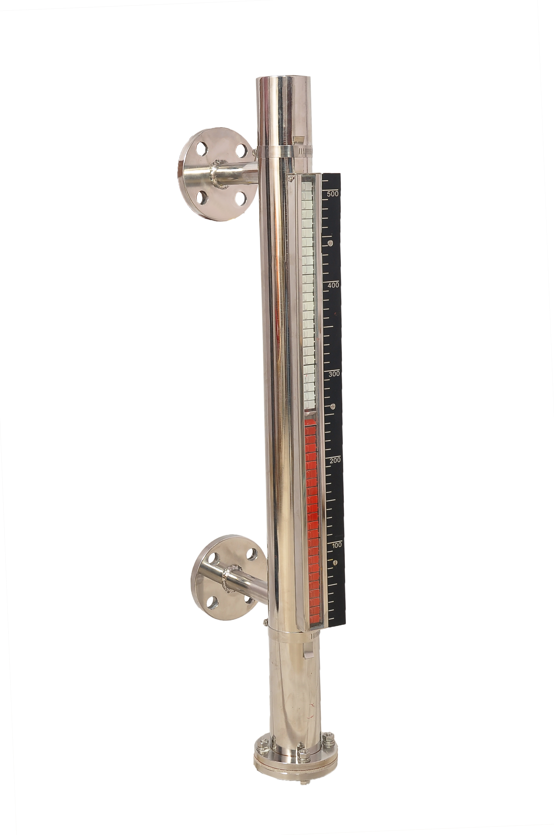 | Level Gauge FILPRO offers Magnetic Level Indicator provides clear, high clarity indication of liquid level. View product → |