Treat the gauge as part of the vessel’s pressure boundary, not as a window that can be bolted on after the tank is ready. You will be able to verify the fit, isolate the vessel, mount the assembly without stressing the glass, test it under controlled conditions and hand it over for safe operation.
Key takeaways
- Confirm pressure, temperature, fluid compatibility and connection dimensions before installation.
- Isolate, drain and depressurise the tank before removing any process connection.
- Tighten evenly and align the gauge without forcing the glass or body.
- Raise pressure gradually and inspect every joint for leaks before service.
Confirm the gauge, glass and tank connection will work together
Treat sight glass level gauge installation as pressure-boundary work, not as mounting a visual indicator. Confirm the tank’s maximum allowable working pressure and temperature, fluid hazards, and compatibility before ordering the gauge.
1. Match the assembled gauge to the service. Check the pressure-temperature rating of the glass, body, valves, drains, gaskets and connections at the actual operating temperature. Use the weakest component as the assembly limit; glass ratings often fall as temperature rises.
2. Verify the tank geometry from a drawing or field measurement. Record the upper-to-lower connection centre distance, nozzle size, flange or thread standard, gasket dimensions, and intended minimum and maximum levels. On a closed vessel, the upper connection normally reaches the vapour space and the lower connection reaches the liquid space.
3. Confirm the wetted materials against the liquid, including corrosive chemicals, solvents, hydrocarbons and cleaning agents. Reject a gauge if the glass, seals or body material is incompatible, or if deposits and condensation will prevent a reliable view.
4. Check the governing code for boilers and regulated pressure service before selection. Boiler rules can specify the number, type, location, isolation fittings and test arrangement for water-level indicators; a general tank gauge may not comply.
5. Ask for the gauge drawing, pressure-temperature data, material details and scale reference. Confirm that the scale matches the connection elevations, with enough lighting and a safe viewing position to avoid parallax or a misleading meniscus.
Before bringing it to the tank, confirm the plant’s pressure or leak-test procedure and never plan a test above the assembled gauge rating. A gauge that passes a static leak check can still show the wrong level if a passage is blocked or its connections are incorrectly referenced.
Isolate, depressurise and prepare the work area
Treat a sight glass installation as pressure-boundary work, not ordinary indicator mounting. Read the vessel’s maximum allowable working pressure and temperature, process hazards, fluid compatibility, and ratings for the glass, body, valves, gaskets, drains, and connections; the weakest component sets the permissible limit, and glass capacity often falls as temperature rises.
1. Stop the process and apply the site lockout/tagout procedure. Close and lock the upper and lower isolation valves, and isolate connected top lines, pumps, steam, gas, electrical actuators, and automatic starts. A handwheel that is merely closed is not positive isolation.
2. Depressurise the vessel through the approved vent and drain route. Drain liquid to a contained, safe location and vent vapour to the plant’s approved discharge point; never loosen a connection to “bleed” pressure.
3. Prove zero pressure at both gauge connections using working pressure indicators or calibrated test points. A gauge that looks empty proves nothing: a blocked drain, trapped liquid, or connected top line can retain pressure.
4. Barricade, ventilate, illuminate, and clear the area of ignition sources when the fluid is flammable. Wear the site-specified eye, face, hand, body, and respiratory protection, and wait for hot surfaces and liquid to reach a safe temperature.
5. Confirm two independently operable isolation valves and a drain or blowdown directed safely. For boiler service, check the governing code before opening the system; its water-level-indicator rules can differ from tank practice.
Only then remove the fitting, loosening bolts or plugs slowly while standing out of the line of fire.
Inspect, mount and align the gauge without loading the glass
Treat sight glass level gauge installation as pressure-boundary work, not simple indicator mounting. Before lifting the assembly, confirm the assembled pressure-temperature rating is not higher than the weakest component. Inspect the glass and guard for damage or seal leakage; replace suspect glass before fitting.
- Position the gauge beside the vessel connections without forcing its ports into line. Leave enough adjustment for gasket seating and enough clearance to remove the glass safely.
- Provide independent supports for the gauge. Do not use its body as a pipe support; piping weight, vibration, thermal expansion or differential movement can distort the body and load the glass or gaskets.
- Fit the specified gaskets and connection hardware, then tighten fasteners gradually in a diagonal pattern. Uneven compression can create a leak or fracture the glass assembly.
- Confirm the scale sits at the intended connection elevations and remains readable from the operating position. Correct the support or piping alignment, not the gauge by pulling it sideways.
- Remove debris and verify that the drains and passages are clear. Complete the plant’s applicable pressure or leak test without exceeding the assembled gauge rating, then check that the indication follows a controlled vessel-level change.
- During commissioning, open the upper and lower isolation valves gradually in the manufacturer’s specified sequence. Warm the gauge progressively; never spray hot glass with cold water.
For boiler service, check the governing boiler code before installation because it can prescribe indicator location, isolation fittings and test arrangements.
Leak-test and commission the gauge gradually
Treat sight glass level gauge installation as pressure-boundary work. Before testing, confirm the assembled gauge remains within the vessel’s pressure and temperature limits; use the lowest rating of the glass, body, valves, gaskets and connections. For boilers or regulated pressure service, follow the governing code and its required test arrangement.
- Remove construction debris and confirm the gauge passages, drains and isolation valves are clear. Check that the guard is fitted and that the glass has no chip, scratch, etching, clouding, star crack, discoloration or seal leakage.
- Perform the plant’s approved pressure or leak test with the gauge isolated or connected as the procedure requires. Never test above the assembled gauge’s lowest rated pressure, and inspect every joint while pressure is held.
- Open the lower and upper isolation valves gradually in the sequence specified by the manufacturer. Let the gauge warm progressively; do not splash hot glass with cold water.
- Compare the scale’s zero and connection elevations with the vessel reference points. A leak-tight gauge can still be blocked or incorrectly referenced.
- Change the vessel level through a controlled range and confirm that the liquid column or indicator follows the change, settles without unexplained delay, and matches an independent level indication. Investigate a fixed or erratic reading before service.
Keep the guard installed during operation, provide independent support, and watch for leakage or glass damage during the first operating period. Return the system to service only after the test record, valve position and level response have been accepted.
Maintain the gauge and choose a different technology when needed
Keep a sight glass level gauge safe in service by treating it as a pressure boundary, not a viewing accessory. Inspect the glass and guard before commissioning and at intervals matched to pressure, temperature, vibration and fluid hazard.
Replace glass with chips, scratches, etching, clouding, star cracks, discoloration or seal leakage; cosmetic damage can reduce its remaining strength. Keep the guard installed and never use it as a step or impact surface.
During sight glass level gauge installation, verify that the weakest component sets the assembly rating: glass, body, valves, gaskets, drains and connections. Rising temperature can reduce the glass rating. For boiler service, check the governing code for the required indicator number, type, location, isolation fittings and test arrangements; ordinary tank practice may not satisfy it.
Keep the viewing area lit and remove deposits or condensation before reading. Check a graduated scale’s zero and span against the connection geometry, because parallax and meniscus effects distort narrow-tube readings.
Filpro Sensors Pvt Ltd should receive the centre-to-centre length, fluid, pressure, temperature and guard requirements when you request a tubular option; those details prevent a neat-looking but wrongly rated selection.
| Option | What it means | When it applies |
|---|---|---|
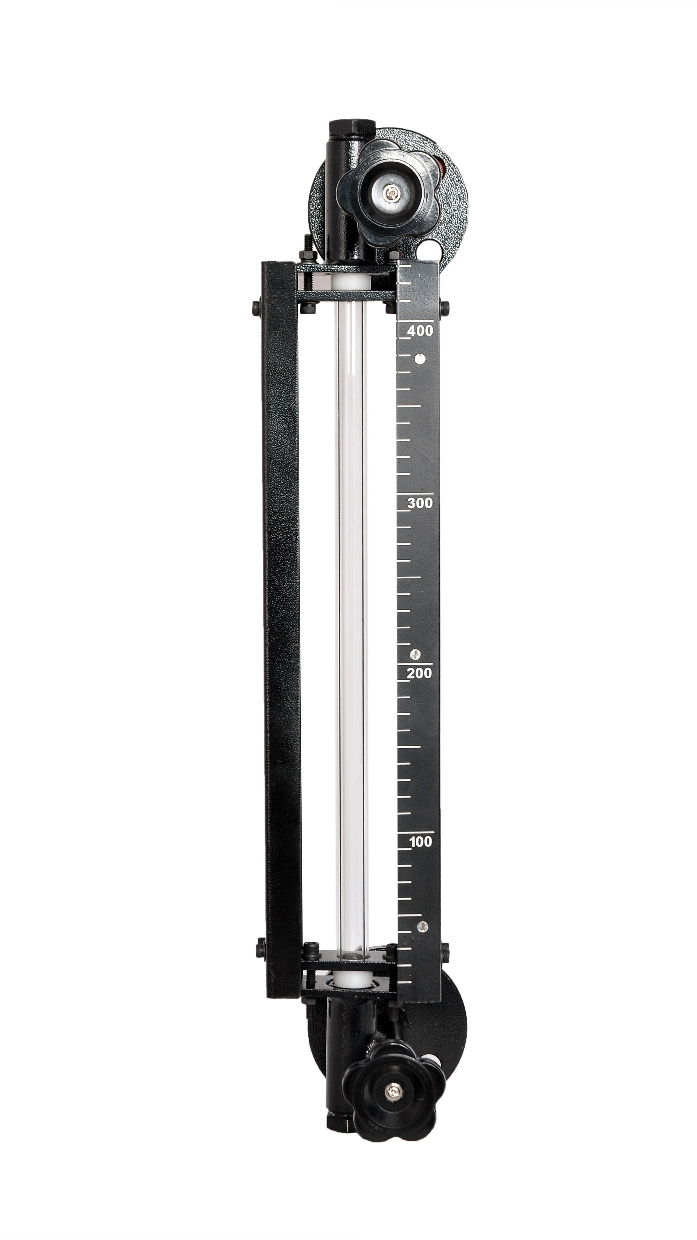
| Tubular | Protected narrow glass tube | Simple, clean, moderate-duty tanks |
| Reflex | Prismatic grooves increase contrast | Clear liquids needing a strong level boundary |
| Transparent | View through the chamber | Coloured liquid, interfaces or two-level indication |
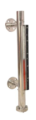
| Magnetic | Float drives an external visual indicator | Dirty, pressurised or hazardous fluids |
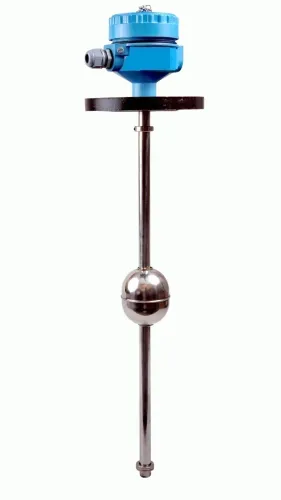
| Electronic | Sensor provides a remote signal | Automation, alarms or inaccessible vessels |
Related product
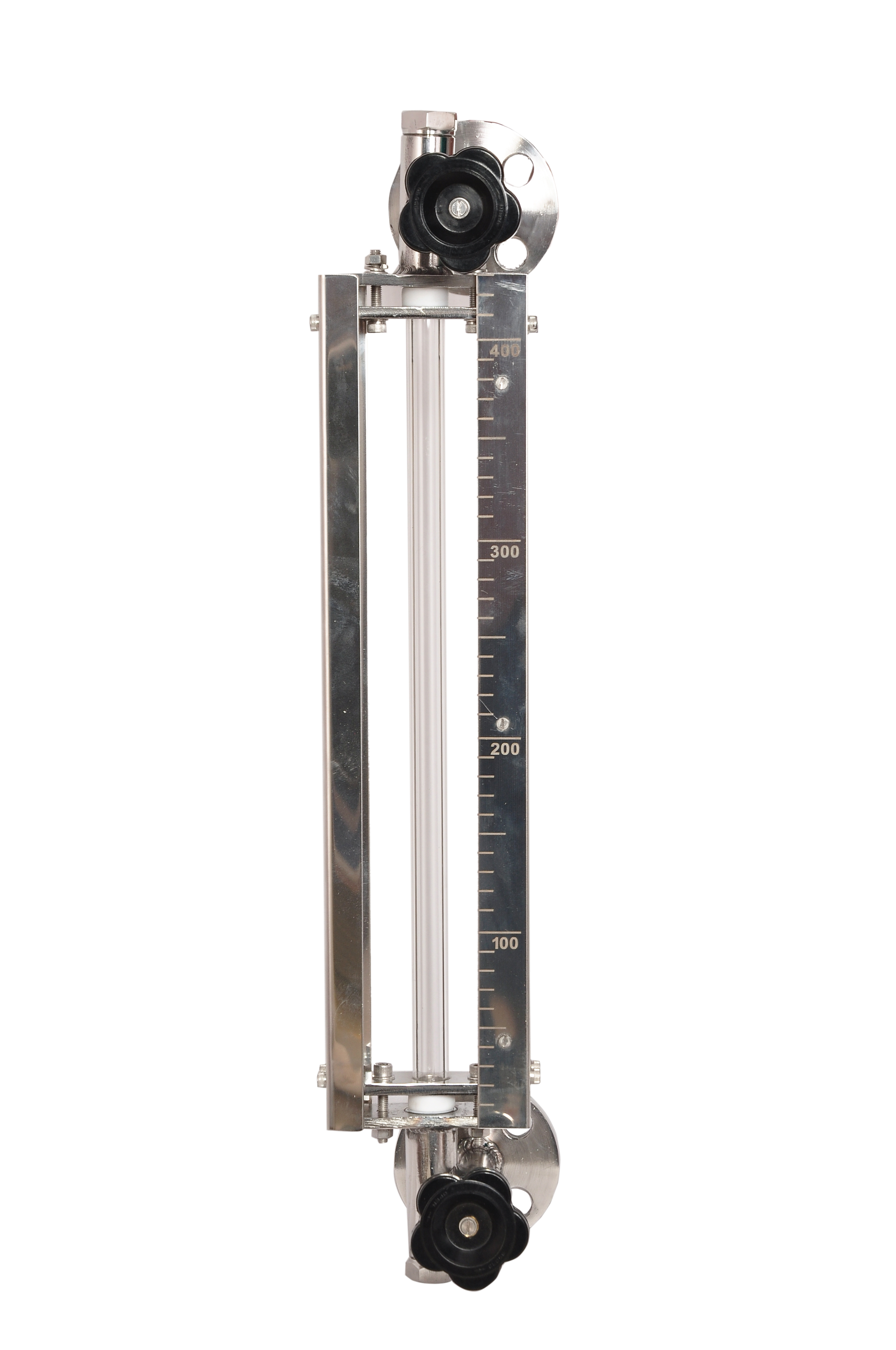 | Level Gauge Tubular Glass Level Indicator is used for visual level indication of liquid in storage and process tanks. View product → |
Frequently asked questions
What must you confirm before installing a sight glass level gauge?
Check the tank’s maximum allowable working pressure and temperature, fluid hazards, glass and gasket compatibility, connection size, flange or threaded standard, centre-to-centre dimensions and visibility requirements.
How do you make the work area safe before installation?
Shut down the process, isolate the tank with lockout and tagout, drain the liquid, depressurise the vessel, verify zero pressure at a safe point and control residual or hazardous fluid.
How do you prevent damage while mounting the gauge?
Inspect the glass, gaskets, bolts and body, clean the mating faces, support the gauge, align it without pipe strain and tighten fasteners gradually in a diagonal pattern to the specified torque.
How should you leak-test and commission a sight glass level gauge?
Restore pressure in stages, inspect the glass seals and process connections at each stage, stop if leakage appears, and confirm the visible level agrees with the tank condition before returning to normal service.
When is a sight glass level gauge the wrong technology?
Choose another level technology when the fluid is opaque, corrosive to the wetted parts, too hot or pressurised for safe viewing, likely to foul the glass, or when remote measurement and automatic control are required.