A 4–20 mA signal is only the final link in a level-measurement system. To select the right transmitter, you must match the sensing principle, calibrated span, process materials, loop capacity, installation and fault handling to the tank and control system.
Key takeaways
- Define the true level span from the tank bottom reference to maximum operating level.
- Choose sensing technology after checking liquid properties, foam, vapour, deposits and tank obstructions.
- Specify loop accuracy, resolution, power supply, load resistance and failure-current behaviour together.
- Confirm process connection, wetted materials, pressure, temperature and hazardous-area requirements before ordering.
Start with the tank, liquid and true measurement span
Begin 4-20 mA level transmitter selection by defining the actual measurement, not by comparing models. Record tank shape, bottom reference, minimum and maximum operating levels, nozzle height, roof clearance, overfill margin, probe insertion length and sensor dead zone.
1. Set the calibrated span from the chosen reference point to the required maximum level. Do not use total tank height unless the transmitter covers that distance. Keep the blocking zone below maximum level; roof or nozzle obstructions can corrupt ultrasonic readings.
2. Document density, viscosity, conductivity, solids, foam, vapour, temperature, pressure, agitation and whether the tank is open or closed. For an open tank, hydrostatic measurement follows ΔP = ρgH, so a 10% density change creates about 10% level error. Closed-tank differential pressure requires vapour-space compensation; wet-leg or dry-leg changes can shift the reading.
3. Include credible surges, shutdown levels and trips without routine operation at either range limit. A narrower span reduces absolute span-based error but reduces turndown and increases overrange risk.
4 mA is a live zero and 20 mA is the calibrated full-scale level. Below-range signals can indicate underrange, wiring trouble or a configured fault; above 20 mA can indicate overrange or an upscale fault.
Check plant NAMUR thresholds, such as about 3.6 mA and 21 mA, and configure the PLC or DCS to distinguish a genuine near-empty level from a fault current.
Choose the sensing technology for the liquid and tank conditions
For 4-20 mA level transmitter selection, compare the sensing method with the liquid and tank conditions, not just the required output.
| Technology | Liquid and tank fit | Main failure conditions |
|---|---|---|
| Float | Clean, low-viscosity liquid; stable density; low foam, vapour, turbulence and temperature | Coating, sticky liquid, heavy solids, vibration, restricted nozzles or an agitator can stop free movement |
| Hydrostatic | Conductive or nonconductive liquid; pressure-rated tanks; unaffected by foam, vapour or obstructions | Changing density, temperature-driven density shifts, turbulence or blocked impulse lines create level errors |
| Ultrasonic | Open, calm tanks with clear acoustic paths and modest vapour | Foam, condensation, dust, angled surfaces, temperature variation, false echoes and acoustic dead zones cause plausible errors |
| Radar | Pressurised, hot or turbulent tanks; foam, vapour, low dielectric liquids and internal structures justify extra commissioning | Poor dielectric response, nozzle geometry, agitators, coils, buildup and false echoes still require antenna and echo mapping |
| Capacitance | Stable dielectric and conductivity, with sound grounding and insulation | Coating, changing dielectric, poor grounding or failed probe insulation shifts the signal |
In an open tank, ΔP is approximately ρgH; changing density requires compensation. In a closed tank, compensate vapour-space pressure: wet-leg condensate or height changes, while a dry leg gains error when vapour condenses. Remote-seal capillary temperature changes also shift ΔP, and elevation must match the tank-bottom reference.
Continuous measurement does not replace independent high-high or low-low point switches.
Match accuracy, resolution and the complete 4–20 mA loop
For a sound 4-20ma level transmitter selection, separate resolution, repeatability, linearity, accuracy and measurement stability. A 5 mm or 10 mm resolution figure is not overall accuracy. Match the error basis—percentage of calibrated span, reading or full scale—to the process tolerance. A narrower calibrated span reduces absolute span-based error but reduces turndown and overrange margin.
For a two-wire loop-powered transmitter, verify the complete budget: V_supply must cover V_transmitter,min + I_maxR_load + cable, barrier and isolator drops. Include cable resistance, receiver input impedance and maximum loop length; a nominal 24 VDC supply can fail at 20 mA.
Use a loop-powered isolator or intrinsically safe barrier where required, and compare two-wire operation with four-wire power-and-signal wiring.
| Signal | Advantage | Limitation |
|---|---|---|
| 4–20 mA | Long, noisy runs; better tolerance of grounding differences | Requires loop-power and compliance-voltage checks |
| 0–10 V | Simple voltage input | Needs compatible input cards and careful grounding |
Specify HART or another protocol, local display, damping, loop calibration, remote configuration, diagnostics and fault-current settings. Choose downscale, upscale or hold-last-value after checking the control-system response and plant NAMUR NE 43 thresholds. Approximately 3.6 mA or lower and 21 mA or higher are common conventions, not universal.
Verify the process connection, materials, ratings and hazardous-area fit
Confirm the flange or thread, nozzle size, mounting orientation and insertion length before ordering. Check float or probe clearance, roof access and removal space; agitators, heating coils and supports can create false echoes or block extraction. For practical 4-20ma level transmitter selection, inspect the actual nozzle geometry, not only the tank drawing.
Select wetted materials from a chemical-compatibility chart for water, diesel, acids, alkalis, solvents and chloride-bearing liquids. Check galvanic corrosion, PTFE suitability, gasket and elastomer compatibility instead of choosing stainless steel or titanium by habit. Verify process and ambient temperature, pressure, diaphragm limits, derating, and remote-seal fill-fluid restrictions at the connection.
Include capillary length and mounting orientation.
| Check | Specify | Failure if missed |
|---|---|---|
| Outdoor or washdown service | Enclosure protection, cable gland, condensation control, UV resistance and earthing | Water ingress, corrosion or unstable signals |
| Hazardous location | Exact ATEX or other certificate, zone or EPL, gas or dust group, temperature class, equipment category and protection concept | Approval mismatch at commissioning |
| Intrinsic-safety loop | Barrier entity parameters for transmitter, barrier, cable and associated apparatus | Approved transmitter still cannot be installed |
| Internal obstacles | Beam path, clearance and removal route | False echoes, fouling or impossible maintenance |
Turn the selection into a comparable specification and lifecycle decision
Write the buyer’s specification before comparing quotes. The signal alone does not identify sensing principle or measurement quality; define each field so a low purchase price cannot hide installation effort.
- Specify medium, density, viscosity, conductivity, solids, foam, temperature, pressure, calibrated range and reference points.
- State accuracy basis, resolution, output and fault-current convention; supply, loop load, HART requirement, process connection, wetted materials and enclosure.
- Record hazardous-area certificate, ambient conditions, cable entry, display, damping, calibration method and required documentation.
| Cost area | Low-price choice | Lower lifecycle risk |
|---|---|---|
| Tank and mounting | Modification, brackets or probe interference | Direct fit with adequate clearance and anchoring |
| Cabling and control | Extra routing, barrier or isolator work, PLC changes | Completed loop-budget and wiring design |
| Commissioning | More false readings and calibration time | Documented calibration and damping settings |
| Maintenance | Moving-part wear, difficult cleaning, scarce spares | Accessible installation, cleaning method and recommended spares |
Request the datasheet, dimensional drawing, wiring diagram, calibration certificate, material certificate, pressure and temperature ratings, hazardous-area certificate, installation manual, loop-load limits and recommended spares. Filpro Sensors Pvt Ltd can translate tank dimensions and process conditions into a documented specification for independent review.
Related products
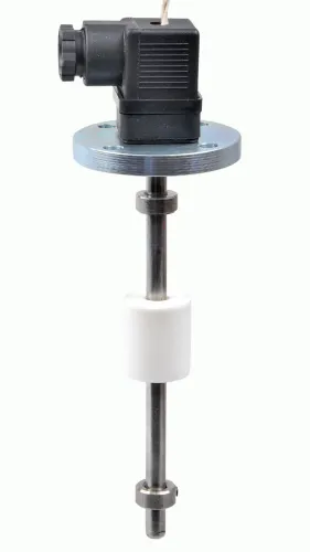
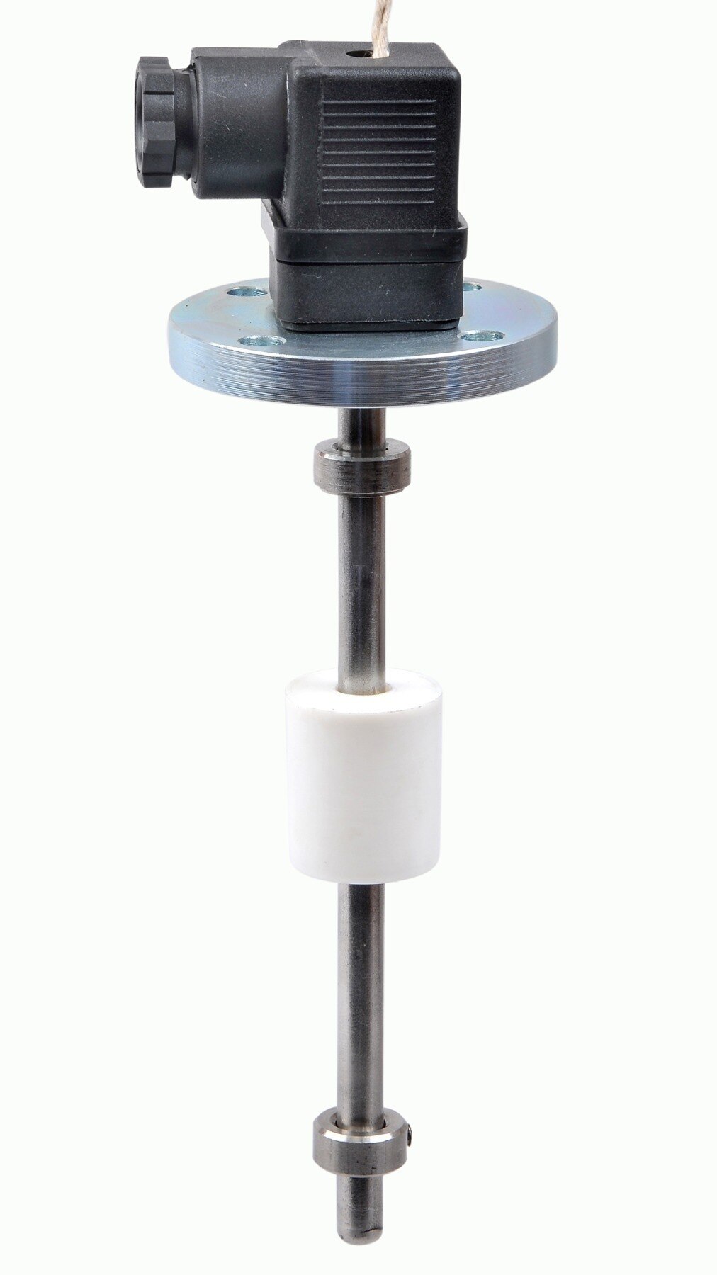
 | Level Sensor Atex approved Float Level Transmitter : Over All Length: 300mm to 5000mm Input: 16V DC to 30V DC Output: 4-20mA / 0-10V DC Resolution: 5mm / 10mm... View product → |
 | Level Transmitter Ultrasonic Level Sensor is a non-contact ultrasonic continuous level measurement product based on sound technology. View product → |
Commission the installed transmitter before accepting the reading
Commission the installed transmitter before accepting its reading. Set and record the lower and upper range values, tank-empty and tank-full references, damping, and fault-current configuration. Bench-test 4 mA and 20 mA, then verify the complete loop at the PLC or DCS input using the actual cable, barrier, isolator, and input resistance.
Compare the indication with a dip, sight gauge, or independent reference where safe.
- For hydrostatic or differential-pressure transmitters, check impulse-line routing, equalizing-valve position, manifold leakage, static-head zero, density, and vapor-pressure compensation. A simulated sensor signal alone is insufficient.
- Test high, high-high, low, and low-low alarms. Confirm that a level near 4 mA is not treated as a sensor fault.
- Check ultrasonic mounting against the dead zone, false echoes, condensation, foam, and turbulence; check radar clearance from internal structures and float travel for obstruction.
- Record calibration data and correct common 4-20ma level transmitter selection errors: using tank height as span, ignoring dead zones, selecting by output alone, and assuming 4–20 mA guarantees accuracy.
| Check | Confirm | Why it matters |
|---|---|---|
| 4 mA and 20 mA | PLC/DCS values | Finds loop scaling errors |
| Fault current | Plant and NAMUR settings | Separates faults from low level |
| Mechanical reference | Independent level | Exposes plausible but wrong readings |
Frequently asked questions
What information should you collect before selecting a 4-20 mA level transmitter?
Record the tank shape, bottom reference, minimum and maximum operating levels, nozzle height, roof clearance, overfill margin, probe insertion length and sensor dead zone.
How do you choose the right level-sensing technology?
Match the technology to the liquid’s dielectric properties, conductivity, foam, vapour, temperature, deposits and the tank’s internal obstructions.
What 4-20 mA loop details must you verify?
Check measurement accuracy, resolution, supply voltage, total loop resistance, output scaling, alarm-current behaviour and compatibility with the receiving instrument.
What must you confirm before installing the transmitter?
Verify the process connection, wetted materials, pressure and temperature ratings, enclosure protection, hazardous-area certification and commissioning settings.
Related products
 | Level Transmitter Hydrostatic liquid level transducers and transmitters with flush diaphragm is designed fora wide variety of level measurement applications. View product → |
 | Level Transmitter Float Level Transmitters Are Ideal For Continuous Level Monitoring In Water, Diesel, Chemical And Oils For Accurate Level Measurement. View product → |
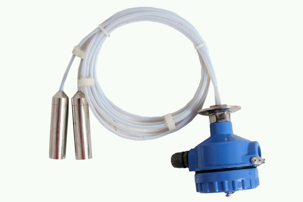 | Level Transmitter can be used for conductive as well as non conductive liquids. View product → |