A reliable calibration starts by identifying the transmitter technology, making the installation safe, and defining the actual zero and span from the tank—not by forcing 4 mA and 20 mA at the transmitter. By following the sequence below, you can test the sensor, loop, display and process reference separately, record defensible as-found and as-left results, and know when calibration will not fix the measurement problem.
Key takeaways
- Match the calibration method to the transmitter’s measurement principle and installation.
- Confirm zero, span, reference datum, process density and pressure limits before testing.
- Test at 0%, 25%, 50%, 75% and 100% of calibrated span.
- Check the transmitter output, loop current, display and alarms after calibration.
What must you check before starting a level transmitter calibration procedure?
Before starting a level transmitter calibration procedure, identify the measurement principle and installation: hydrostatic or differential-pressure (DP), radar, ultrasonic, capacitance, float, or another technology. The reference input and error sources differ, so a pressure test is wrong for radar or ultrasonic.
| Technology | Check before calibration |
|---|---|
| Hydrostatic or DP | Density, pressure-reference conditions, wet-leg fill and trapped gas; both high- and low-side connections |
| Radar | Antenna reference point, tank geometry, obstruction clearance and false-echo setup |
| Ultrasonic | Clear acoustic path, tank height, blocking distance, foam, vapour and agitators |
| Capacitance | Insertion depth, probe condition and coating compensation |
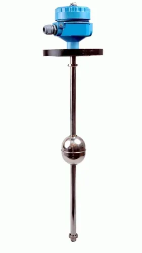
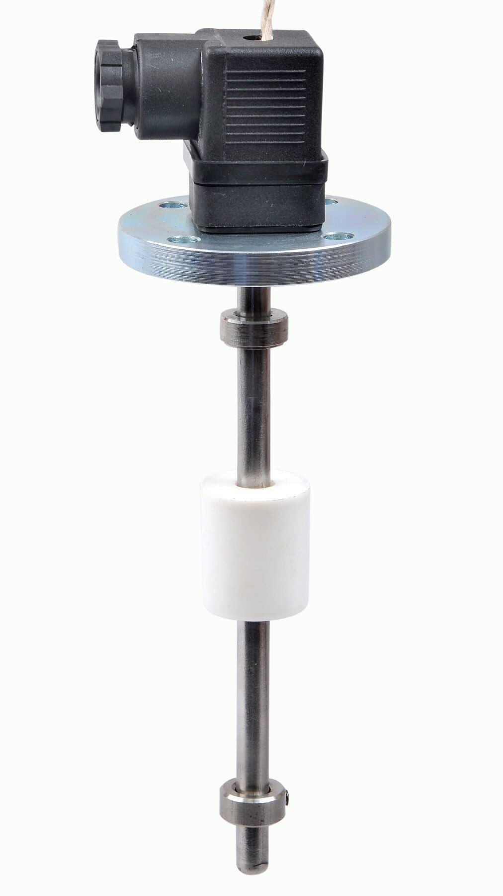
| Float | Mechanical zero, float travel and unobstructed movement |
Use this level transmitter safety checklist before disconnecting anything:
- Apply lockout/tagout and electrical isolation, obtain the required work permit, and confirm zero electrical, pressure and stored process energy.
- Treat toxic, flammable, hot or pressurised liquid as a process hazard. Drain, vent and depressurise the instrument and impulse lines before opening connections.
- Arrange confined-space entry controls and gas testing before tank access.
- For ATEX level transmitter calibration, check the equipment group, category, temperature class and protection method. Do not open, disconnect or remove equipment in the classified area unless the permit and site procedure allow it; move it to a safe area when required.
Inspect cable polarity, supply voltage, grounding, loop resistance, mechanical zero, high-side and low-side pressure connections, blocked impulse lines and a fouled flush diaphragm. Confirm the radar datum, ultrasonic reference point and configured vessel zero before applying any reference.
How do you establish the correct reference level, pressure and range?
Establish the correct reference level, pressure, and range from the actual installation before connecting test equipment. Define the 0% datum as the tank bottom, diaphragm elevation, probe tip, lower tap, or another plant datum, then record:
1. Nozzle height, empty-tank distance, transmitter elevation, blocking distance, and any existing zero offset.
2. Derive the configured lower-range value (LRV) and upper-range value (URV) from the actual 0% and 100% levels. Do not enter zero and the sensor’s maximum range automatically; a transmitter below the lower tap needs zero suppression, while one above it can need zero elevation.
3. For a hydrostatic level transmitter, calculate expected differential pressure with ΔP = ρgΔh. Include liquid specific gravity, gravitational acceleration, transmitter elevation, and whether the reference leg is dry or filled. A wet leg needs the specified liquid at known density, trapped gas removed, and protection against evaporation, condensation, contamination, and temperature-driven density change.
4. On a closed vessel, apply equal static pressure to both sides through the impulse connections or remote seals. Pressurising only the high side does not reproduce service conditions. Use a traceable pressure calibrator or measured reference column for pressure devices.
For radar and ultrasonic transmitters, use a known liquid level or measured distance, accounting for tank geometry, sensor reference point, blocking distance, foam, vapour, agitators, and false echoes. Wet calibration raises liquid to marked levels; dry calibration uses a pressure source or simulator. A simulated electrical input checks electronics, not the installed sensor.
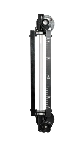
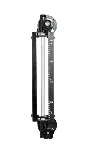
A float-and-board indicator offers visual comparison, but its pointer, rope, pulleys, and board add mechanical errors and provide no 4–20 mA signal.
What sequence and test points should you use?
First isolate the transmitter from the process, make the tank safe, and confirm the manifold or isolation-valve sequence. For a DP device, block, equalise, vent and connect the pressure calibrator without sending test fluid into the vessel.
- Connect a regulated DC supply, calibrated multimeter or loop calibrator, and communicator or configuration software where digital communication is available.
- Apply the reference input slowly and wait for pressure, liquid level and output to stabilise.
- Record increasing and decreasing readings at 0%, 25%, 50%, 75% and 100% of configured span. In a linear loop, 4 mA represents the LRV and 20 mA represents the URV.
- Check damping, square-root extraction, nonlinearisation and diagnostic current limits before judging the reading.
| Instrument | Reference used | Checks that govern the test |
|---|---|---|
| DP | Applied pressure | Manifold state, pressure stability and calibrated span |
| Radar or ultrasonic | Measured distance or liquid level | Tank height, reference datum, blocking distance, probe or antenna position, false-echo map, foam and vapor |
| Capacitance | Known level or simulated condition | Coating and dielectric assumptions |
| Float | Mechanical level movement | Free movement and mechanical zero before electrical output |
Use sensor trim only for a proven sensor-pressure error and output trim only for a proven analogue-output error. Neither corrects an incorrect range or installation datum. For 4–20 mA calibration, compare the display, loop current, control-system value, engineering-unit scaling, alarm limits and failure-current behaviour.
Adjust only after recording as-found values. Repeat the complete sequence as-left, recording applied references, readings, error, conditions, tag, range, trims and pass/fail limits.
How do you verify the loop, display and calibration result?
A 4–20 mA loop test verifies the complete signal path, not the liquid measurement itself. During the level transmitter calibration procedure, force or apply 0%, 50% and 100% input, then compare each result across the loop.
| Check | Expected comparison | What a failure indicates |
|---|---|---|
| Transmitter display | Applied level matches displayed engineering-unit value | Sensor, configuration or transmitter error |
| Measured loop current | 4.00, 12.00 and 20.00 mA at the configured points | Output, wiring or power-supply error |
| Control-system value | Matches the transmitter value in the correct units | Input-card scaling or unit-conversion error |
| Alarm limits | Alarms operate at their configured setpoints | Incorrect limits, logic or scaling |
| Failure current | Diagnostic current matches the configured fault behaviour | Fault signalling is misconfigured or untested |
For a 0–5 m range, expected outputs are 4 mA at 0 m, 12 mA at 2.5 m and 20 mA at 5 m. Calculate observed level as level = (measured current − 4) × 5 ÷ 16. A 12.16 mA reading gives 2.55 m, which is 50 mm above midpoint.
Account for damping, output limits and nonlinearisation.
Record the reference input, transmitter reading, current, calculated level transmitter error and pass/fail result at every upscale and downscale point. Use the manufacturer’s accuracy specification, site requirement and a traceable reference; do not invent a tolerance.
Preserve the as-found as-left calibration record with tag, range, units, equipment ID, date, technician, conditions, trims, damping and next due date. If it fails, record as-found error, investigate fouling, damage, trapped gas, wiring and configuration, correct and retest.
Quarantine it if reliability remains uncertain, assess affected batches and decisions, then restore covers, valves, grounding, barriers and normal configuration.
When should you recalibrate, and when will calibration not solve the problem?
Recalibrate after commissioning, sensor replacement, wiring changes, tank-geometry changes, process changes or corrective maintenance. Set the level transmitter calibration frequency from drift history, service severity, regulatory or quality requirements, and the consequence of an incorrect level—not from an unsupported universal period.
| Event | Required check | Main risk |
|---|---|---|
| Commissioning | Verify datum, range, loop and display | A correct sensor can show the wrong tank level |
| Sensor replacement | Confirm configuration and complete as-left testing | Old settings or a missed trim can remain active |
| Wiring changes | Perform a complete loop test | Signal polarity, scaling or failure current can be wrong |
| Tank-geometry change | Review datum, height, zero, span and false echoes | The transmitter can measure correctly against the wrong geometry |
| Process change | Review density, dielectric, temperature and pressure | The measurement principle or range may no longer suit the service |
| Corrective maintenance | Repeat as-found and as-left tests | A repair can mask an unresolved installation fault |
Calibration will not remove the level transmitter limitations caused by foam, vapour, condensation, turbulence, agitation, buildup, dead zones, a floating roof or an agitator.
For radar, review antenna geometry and false echoes; for ultrasonic, acoustic path and blocking distance; for capacitance, coating and changing dielectric; for hydrostatic instruments, density, blocked diaphragms and reference-leg condition; for float instruments, obstruction, magnet damage and float travel.
Before level transmitter selection, compare reference-equipment needs, tank shutdown, adjustment access, output protocol, hazardous-area approval, accuracy, resolution, temperature and pressure limits, wetted materials and calibration-record support. Filpro Sensors Pvt Ltd is worth assessing when its technology can be matched to a maintainable verification method rather than headline accuracy alone.
Related products
 | Level Transmitter Float Level Transmitters Are Ideal For Continuous Level Monitoring In Water, Diesel, Chemical And Oils For Accurate Level Measurement. View product → |
 | Level Sensor Atex approved Float Level Transmitter : Over All Length: 300mm to 5000mm Input: 16V DC to 30V DC Output: 4-20mA / 0-10V DC Resolution: 5mm / 10mm... View product → |
Frequently asked questions
What must you check before starting a level transmitter calibration procedure?
Identify the sensing technology, installation arrangement, tag, range, units, process conditions and approved isolation procedure. Use a pressure source for hydrostatic or DP transmitters, not for radar or ultrasonic instruments.
How do you establish the correct reference level, pressure and range?
Confirm the tank datum, zero level, upper reference point, liquid density, impulse-line elevations and configured lower and upper range values. Convert the reference level into the correct pressure or simulated input for the transmitter.
What sequence and test points should you use?
Apply test points in an increasing sequence at 0%, 25%, 50%, 75% and 100% of span, record the output, then repeat in decreasing order to identify hysteresis.
How do you verify the loop, display and calibration result?
Compare the transmitter output with a calibrated reference, check 4–20 mA values, confirm the PLC or DCS display, inspect alarms and verify the final reading after returning the process to service.
When should you recalibrate, and when will calibration not solve the problem?
Recalibrate after failed verification, maintenance, sensor replacement, configuration changes or a defined maintenance interval. Calibration will not fix blocked impulse lines, damaged probes, foam, turbulence, density changes, poor grounding or incorrect installation.
Related products
 | Level Transmitter Hydrostatic liquid level transducers and transmitters with flush diaphragm is designed fora wide variety of level measurement applications. View product → |
 | Level Transmitter Ultrasonic Level Sensor is a non-contact ultrasonic continuous level measurement product based on sound technology. View product → |
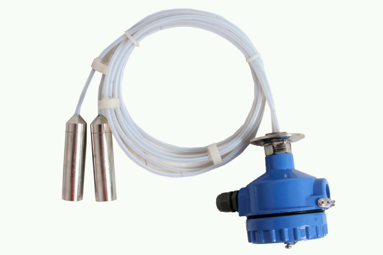 | Level Transmitter can be used for conductive as well as non conductive liquids. View product → |
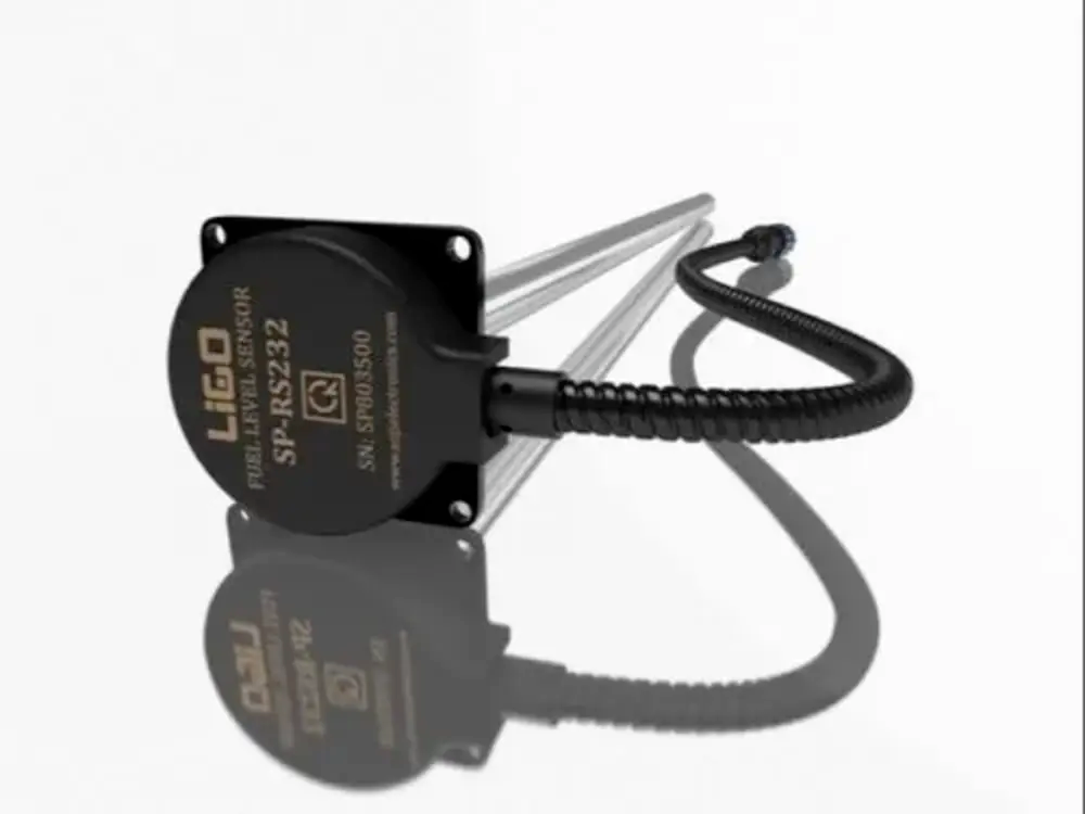 | Level Sensor Ligo fuel sensor for monitoring Diesel and Petrol level in vehicle fuel tanks and DG sets. View product → |