A tank operator needs a continuous level signal, but the pressure at the tank bottom does not reveal height unless liquid density and vessel pressure are understood. By the end, you will be able to identify the transmitter’s practical uses, choose the correct pressure reference and range, and avoid installation conditions that create false level readings.
Key takeaways
- Measure liquid height from pressure, not surface detection.
- Use gauge pressure for open tanks and differential pressure for sealed vessels.
- Keep the sensing diaphragm clear of deposits, bubbles and turbulent flow.
- Match the pressure range and wetted materials to the liquid.
What a hydrostatic level transmitter measures and controls
A hydrostatic level transmitter measures liquid height indirectly: it senses the pressure created by the liquid column at its diaphragm or probe elevation, then converts that pressure into a level signal. It does not see the liquid surface.
The relationship is ΔP = ρgh, where ΔP is pressure, ρ is liquid density, g is gravitational acceleration, and h is liquid height. Pressure therefore depends on density as well as height. The same pressure represents different levels in water, oil, brine, acid, or another liquid because each has a different density.
Common hydrostatic level transmitter applications include:
- Monitor level continuously in tanks, wells, sumps, reservoirs, and process vessels.
- Estimate tank inventory from level and tank geometry.
- Start or stop transfer and drain pumps at configured levels.
- Trigger high- and low-level alarms through a PLC or control system.
- Track process conditions where liquid level affects flow, mixing, heating, or dosing.
That is the hydrostatic level transmitter meaning in plain language: infer height from liquid-head pressure. The calculation assumes a calibrated density. If calibration uses 1,000 kg/m³ but the actual liquid becomes 10% denser or lighter, the indicated level can carry about a 10% proportional error for the same pressure.
Temperature, concentration, mixing, or composition changes can therefore shift the reading even when the surface does not move.
Choosing the pressure reference for open and sealed vessels
Choose the pressure reference from the vessel design, not from the sensor label alone.
| Option | What it measures | When it applies |
|---|---|---|
| Gauge pressure | Pressure above local atmosphere | Open or vented tanks |
| Absolute pressure | Pressure above a perfect vacuum | Applications requiring total pressure, not ordinary level reference |
| Differential pressure | Difference between two pressure points | Sealed or pressurised vessels |
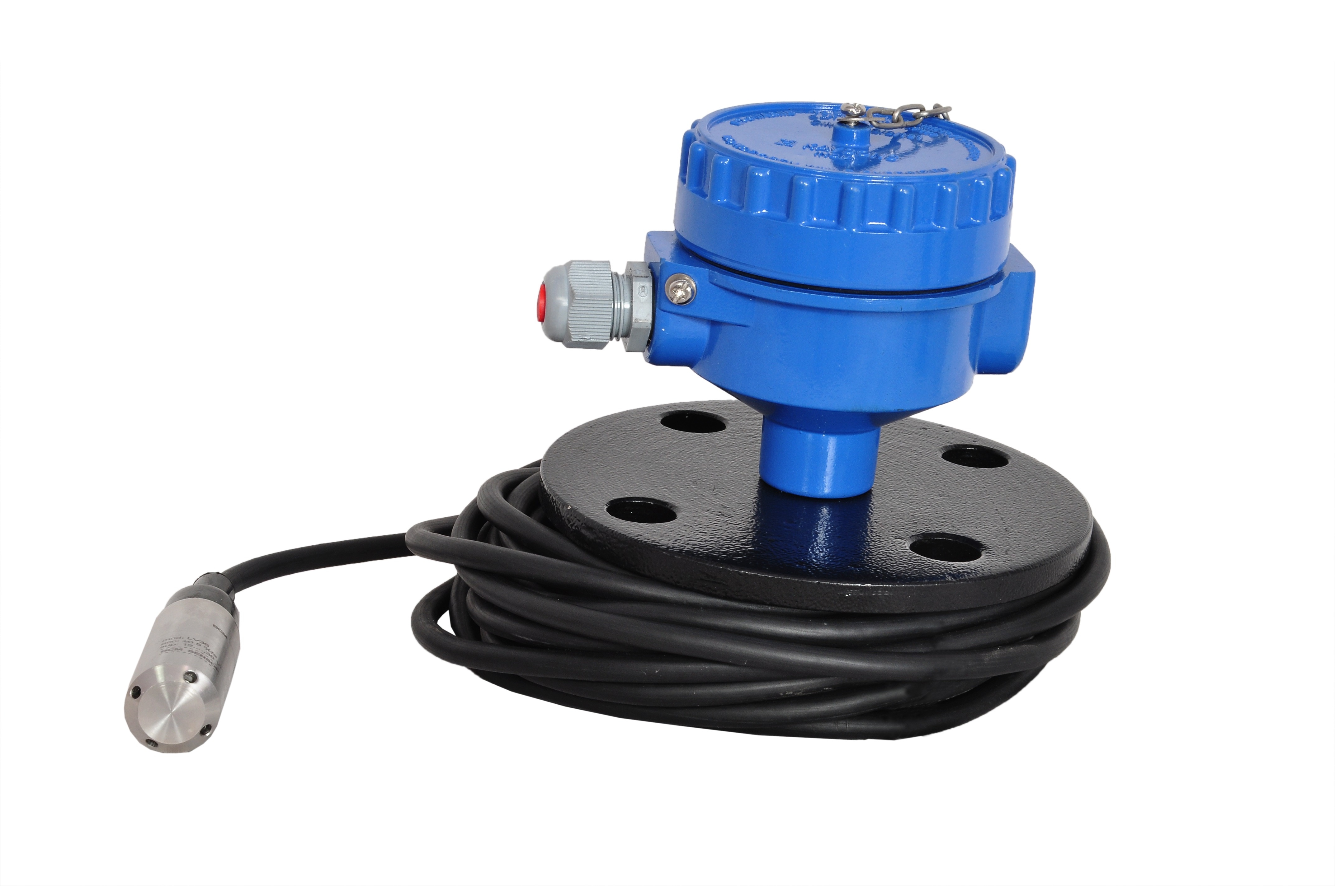
In an open tank, a gauge-pressure transmitter installed at or near the bottom measures the liquid head. Atmospheric pressure acts on the liquid surface and the transmitter’s reference side, so it cancels. A submersible hydrostatic level transmitter sits near the lowest required measurement point; its vented cable supplies atmospheric reference.
Keep the vent tube open and protect it from kinks, flooding, blockage and contamination, which can cause offset, slow response or false level changes. An external transmitter instead connects to the vessel through a diaphragm seal or impulse line.
A sealed vessel needs a differential-pressure transmitter. Its high side senses liquid-head pressure at the lower connection, while its low side senses vapour-space pressure at the upper connection. Subtracting vapour pressure leaves the pressure caused by liquid height. A gauge transmitter would interpret changing vapour pressure as a level change.
Absolute pressure is not a substitute: it includes atmospheric pressure and vapour pressure without providing the vessel’s correct pressure reference.
Installing the sensor without creating a false level signal
A false level signal usually starts with the sensing point, not the electronics. The transmitter measures pressure at its diaphragm or probe elevation, so installation height and configured zero must match.
1. Mount a submersible probe near the lowest required measurement point, without resting it in sludge. Record the sensing-port elevation, then set zero and span for that installed position and maximum liquid height. Moving the probe later, or leaving the original zero after relocation, creates a fixed level offset.
2. Route the probe cable away from agitators, sharp edges, heat and pump discharge. Secure it with strain relief and use a protective cage where impact is possible. Keep the atmospheric vent open; a kinked, flooded, blocked or contaminated vent tube causes slow response, drift or an apparent level change.
3. For an external transmitter, install an isolation valve at each pressure connection so you can remove and test it safely. Keep impulse lines short, supported and continuously sloped where possible; avoid high points that trap gas and low points that collect condensate or liquid. In hot service, condensate can create a false pressure head.
4. Place the sensing point away from pump turbulence, agitators and direct discharge. Sludge or sediment can bury the diaphragm and make the indicated level stay high.
Use a stilling well for calmer measurement, a protective cage for impact, a remote seal for difficult process conditions, or a flush arrangement when deposits would plug a recessed port.
These details determine reliable hydrostatic level transmitter applications more than the display range alone.
Sizing the range and wetted materials for the liquid
Set the pressure span from maximum liquid height and expected density, not tank height alone. Use ΔP = ρgh: a 10 m column of water produces about 100 kPa, while oil, brine, or acid at the same height produces a different pressure.
Include the highest operating density and level, or the transmitter can overload or saturate.
| Span choice | Consequence |
|---|---|
| Too narrow | Pressure above the calibrated span clips the output, overloads the sensor, or hides a high-level condition. |
| Correctly matched | The full operating level fits the range while preserving usable resolution. |
| Unnecessarily wide | The same absolute pressure error represents more level uncertainty, reducing usable resolution. |
For 10 m of water, a 100 kPa span with 0.1% span error produces about 0.1 kPa, or roughly 10 mm of water-level uncertainty, before density and temperature effects. Treat transmitter accuracy, density variation, and temperature drift as one level-accuracy calculation.
Specify wetted construction for the actual liquid, not simply “stainless steel.” Chemical attack, solvent exposure, wastewater fouling, abrasive slurry, suspended solids, and sediment can coat, plug, erode, or bury the sensing diaphragm. Ask for:
- Stainless-steel grade and compatibility limits
- Diaphragm material and protective coating
- Remote seal or flush sensing face
- Abrasion, fouling, temperature, and pressure limits
A hydrostatic level transmitter need is weak when the liquid chemistry or density changes beyond the calibration basis; choose protection that matches the failure mechanism.
When hydrostatic measurement is the right practical choice
Choose a hydrostatic level transmitter when the liquid’s density is known and the sensing point remains accessible. Strong hydrostatic level transmitter applications include water and wastewater tanks, wells, boreholes, lift stations, sumps, reservoirs, chemical storage tanks, and process vessels.
1. Confirm the surface is difficult to read without contact. Foam, vapour, dust, condensation, and poor optical conditions can disrupt ultrasonic or reflected-signal instruments; liquid-head pressure continues to provide a signal because it does not depend on a reflected wave.
2. Test whether the hydrostatic level transmitter need is strong. Choose another method, or measure density separately, when concentration, temperature, mixing, or composition changes substantially. Treat highly corrosive or fouling liquids, hard-to-maintain impulse lines, and processes where contact is unacceptable as warning signs for a non-contact instrument.
3. Reject hydrostatic measurement for dry bulk solids. Changing bulk density, bridging, and air-filled voids make pressure-to-height conversion unstable, so an indicated level can shift without a corresponding surface movement.
4. Give a manufacturer such as Filpro Sensors Pvt Ltd enough operating detail to select the instrument: tank height, liquid-density range, temperature, pressure, chemistry, solids content, mounting point, required alarm accuracy, and whether the vessel is vented or sealed.
Missing any of these details can produce a transmitter that works on the test bench but gives unreliable alarms in service.
Related product
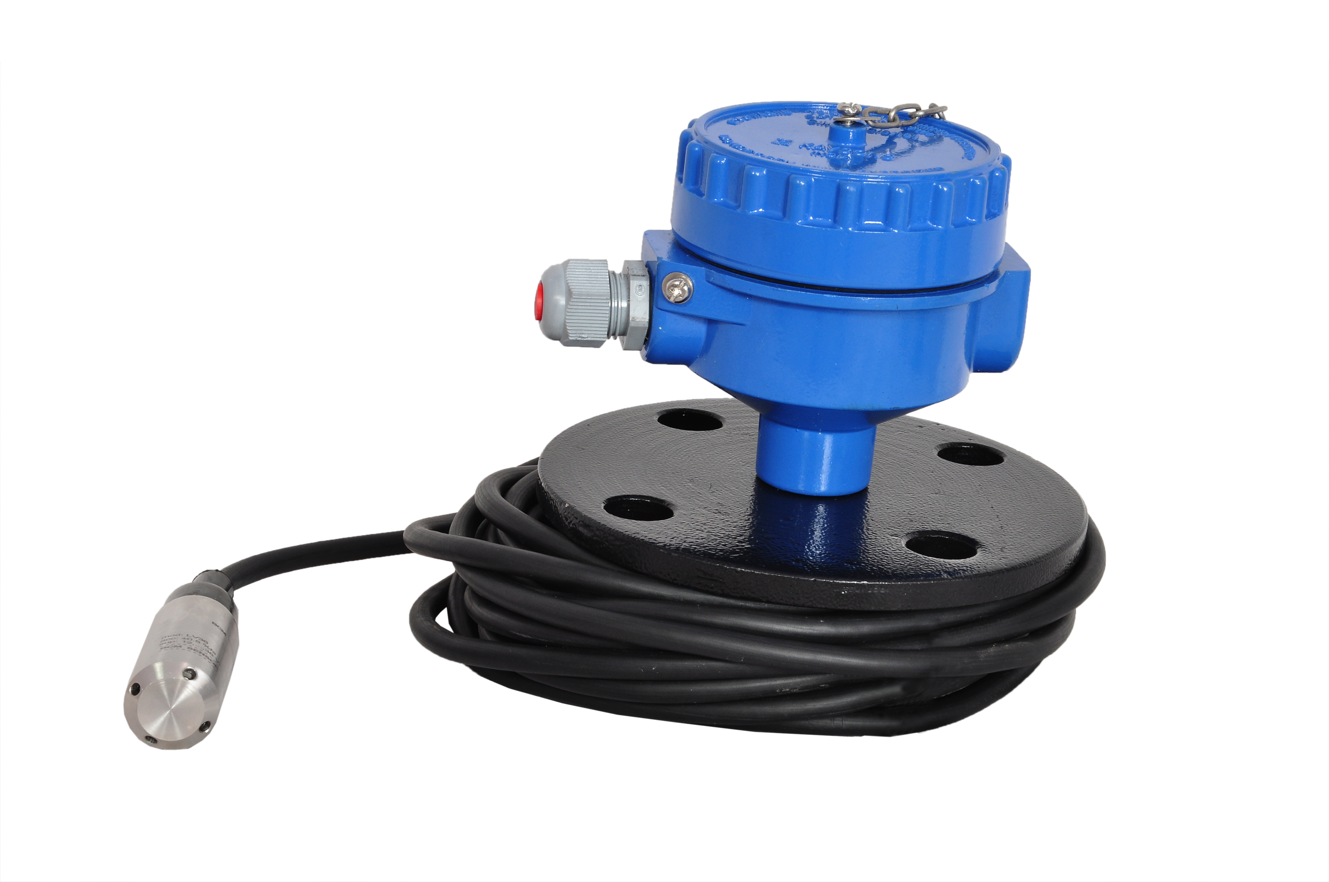 | Level Transmitter Hydrostatic liquid level transducers and transmitters with flush diaphragm is designed fora wide variety of level measurement applications. View product → |
Frequently asked questions
What does a hydrostatic level transmitter measure?
It measures pressure from the liquid column above the sensor and converts that pressure into a level signal.
Which pressure reference suits an open tank?
Use gauge pressure referenced to atmospheric pressure for an open tank.
Which pressure reference suits a sealed vessel?
Use differential pressure with a reference connected to the vessel vapour space when gas pressure changes above the liquid.
How do you prevent a false level signal during installation?
Install the sensor at a stable sensing point, keep the diaphragm clear of deposits and bubbles, and protect it from turbulence.