The correct instrument depends on more than tank height: pressure, temperature, density, turbulence, visibility, hazardous-area classification and the signal your control system needs all affect the choice. By the end, you will be able to define the measurement range, reject unsuitable technologies and prepare a specification that can be checked against the vessel and process conditions.
Key takeaways
- Define continuous measurement, local indication or point-level alarm first.
- Check pressure, temperature, density, viscosity and solids before choosing technology.
- Compare visibility, accuracy, maintenance access and full installed cost.
- Specify range, connections, materials, ratings and hazardous-area safeguards in writing.
Start with the measurement job, not the instrument name
Start with the measurement job: do you need a continuous value, a local reading, or a point-level alarm? A level indicator for process vessels does not automatically provide level control; control also needs an output, controller and final control element.
- Choose continuous measurement when you need a live value for trending, batching, inventory, or automatic valve or pump control. Radar, guided-wave radar, ultrasonic, differential-pressure and displacer instruments can provide this signal, but check the usable range against the vessel nozzle and the instrument’s dead or blocking zone. A nominal tank height is not the same as measurable range.
- Choose local visual indication when an operator needs to see level at the vessel. A magnetic level gauge keeps liquid inside an external chamber and needs no powered signal loop, but select its float for the liquid’s density, pressure, temperature and viscosity. Coating, solids or a damaged float can make the display stick or decouple from actual level.
- Choose point-level switching when you need a high-high trip, low-level pump protection or overfill alarm rather than a percentage reading. Conductivity probes need a conductive liquid; conventional probes will not detect nonconductive hydrocarbons. Capacitive probes introduce different concerns, including dielectric constant and coating.
- Treat float-and-tape indicators as simple local devices, not automatic control instruments. Friction, guide obstruction, tape stretch and pulley wear can create delayed or incorrect movement.
For differential-pressure measurement, verify density assumptions: a calibration based on specific gravity 1.0 reads about 25% low when the actual specific gravity is 0.8.
Match the technology to pressure, temperature and fluid behaviour
Choose the technology that tolerates the vessel’s pressure and temperature across the entire operating cycle, not just the transmitter body rating. Specify the chamber, float or displacer, probe, seals, glass, gaskets, isolation valves and remote-seal fill fluid for pressure, corrosion, erosion, vacuum, thermal cycling and fugitive-emission limits.
| Technology | Pressure and temperature fit | Fluid behaviour and failure risk |
|---|---|---|
| Magnetic level gauge | Select the chamber and float for the vessel’s maximum pressure and temperature | Works without a powered loop, but incorrect density, viscosity, coating, solids or magnetic incompatibility can make the external flag stick or decouple |
| Differential pressure | Suitable when impulse connections and seals match process pressure and temperature | Output follows liquid height and specific weight; a change from specific gravity 1.0 to 0.8 can make a fixed calibration read about 25% high |
| Radar | Strong choice across changing density and many pressure or temperature conditions when the antenna rating matches | Foam, agitators, vapour, buildup and a poor nozzle can create false echoes or lose the surface echo |
| Ultrasonic | Use only where vapour conditions stay within the instrument’s specified range | Temperature gradients, pressure changes, condensation, dust, foam and turbulence distort sound travel |
Radar avoids the density error of hydrostatic measurement because it measures distance to the surface. Ultrasonic is noncontact too, but changing vapour composition or persistent foam makes it a poor default.
A local sight glass or magnetic level gauge shows level without a control signal. If automation is required, add a transmitter, controller and final control element; a point-level switch alone cannot replace continuous indication.
Compare accuracy, visibility, maintenance and installed cost
A level indicator for process vessels should be compared on four practical tests: accuracy, visibility at the vessel, maintenance burden and installed cost. The table shows the usual trade-offs in service.
| Option | Accuracy | Visibility | Maintenance | Installed cost |
|---|---|---|---|---|
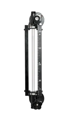
| Tubular glass | Moderate; local reading only | Direct and immediate | Glass cleaning, breakage checks and isolation-valve care | Low |
| Magnetic | Moderate to good; depends on float selection | Clear external scale, even from a distance | Inspect float movement, chamber fouling and indicator sticking | Medium |
| Float-and-board | Moderate; best for large outdoor tanks | Visible from ground level | Cable, pulley, float and weather exposure need attention | Low to medium |
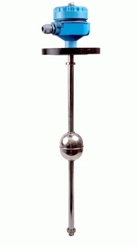
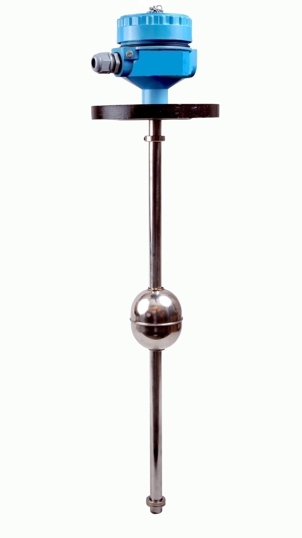
| Float transmitter | Moderate; provides a continuous signal | Local display depends on model | Mechanical float and transmitter require calibration and inspection | Medium |
| Hydrostatic | Good when liquid density stays stable | Remote display; no direct sight of level | Impulse lines, seals and zero drift need maintenance | Medium |
| Radar | Good to high; continuous electronic output | Remote display, with optional local display | Low routine maintenance; check antenna fouling and dead zone | High |
| Ultrasonic | Moderate; degrades with foam or changing vapour conditions | Remote display | Low contact maintenance, but condensation and signal loss need checks | Medium |
Tubular glass, magnetic and float-and-board instruments show level locally but do not provide a control signal. Float transmitters, hydrostatic, radar and ultrasonic instruments support control only when paired with an output, controller and final control element.
Choose radar over ultrasonic when foam, vapour changes or condensation are persistent. For radar, check the nozzle and maximum level against the stated blocking distance, not tank height alone. A higher purchase cost can reduce access, cleaning and calibration work.
Specify the range, connections and installation before you buy
A usable level range is set by the vessel’s minimum and maximum levels, nozzle position, and instrument blocking distance—not by tank height alone. Specify the distance from the process connection to each level you need to measure; if either point enters a radar antenna’s or guided-wave probe’s dead zone, the advertised range is unattainable.
1. Record the vessel’s internal diameter and straight-side height, plus minimum and maximum operating levels, roof or bottom shape, and the position of coils, agitators, dip pipes, baffles, and other obstructions. These details expose false echoes, stagnant pockets, and unmeasured zones.
2. Specify the nozzle size, neck length, flange or threaded connection, allowable probe or float intrusion, and clearance above the highest liquid level. A long or poorly positioned nozzle can put a sensor in an echo dead zone; a side chamber can show a level that does not represent the vessel.
3. State whether you need isolation valves, a drain, vent, flushing connection, heat tracing, or cleanout access. Include foam, vapour, buildup, and expected solids so the installation remains serviceable.
4. Confirm the output you need. A sight glass or magnetic level gauge gives local indication; continuous control requires a transmitter, controller, and final control element.
Filpro Sensors Pvt Ltd can help translate these dimensions into a gauge, float arrangement, or transmitter specification, but approve the nozzle drawing and calibrated range before ordering. Choose a level indicator for process vessels against actual vessel conditions, not the instrument label.
Related products
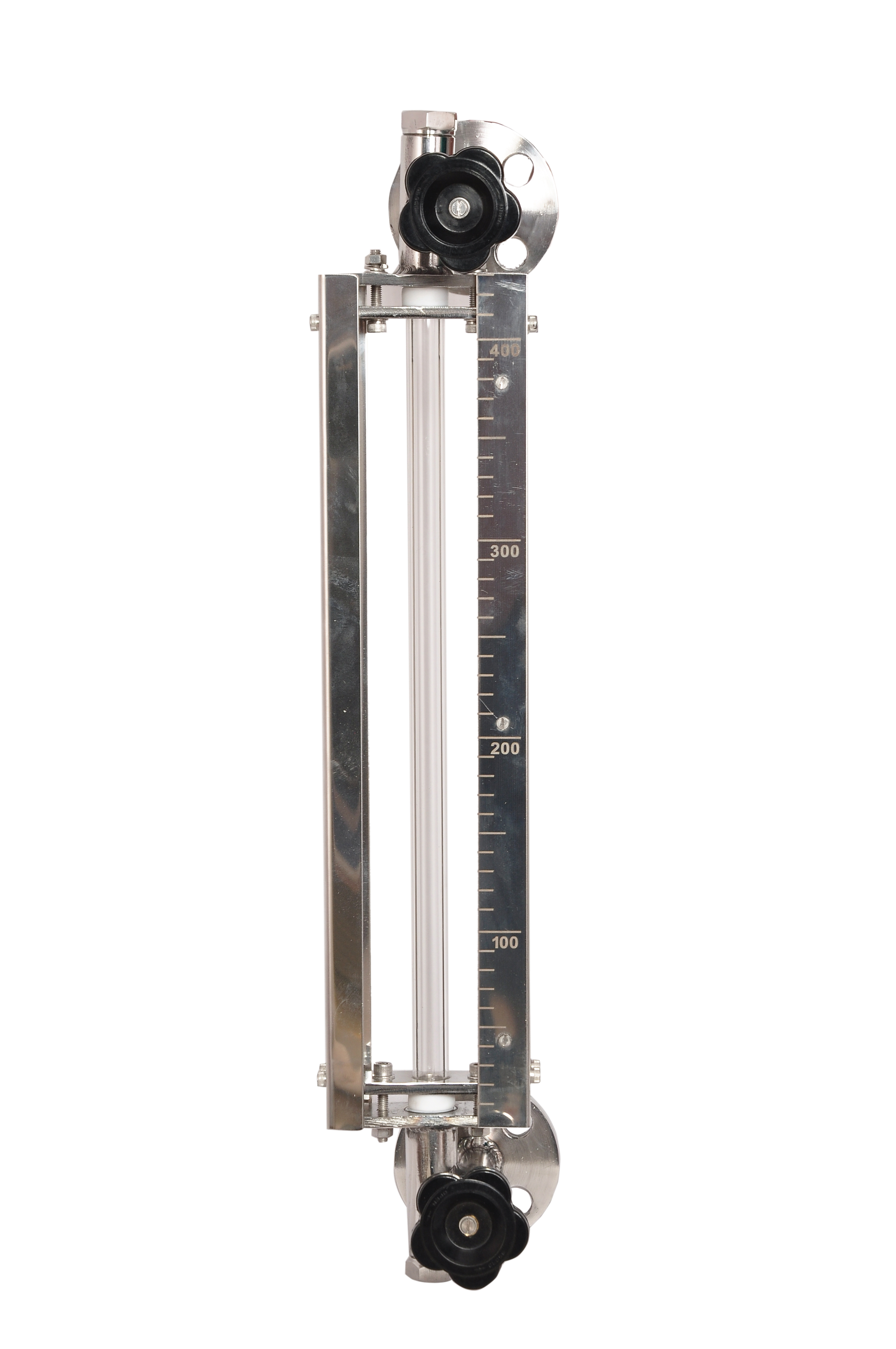 | Level Gauge Tubular Glass Level Indicator is used for visual level indication of liquid in storage and process tanks. View product → |
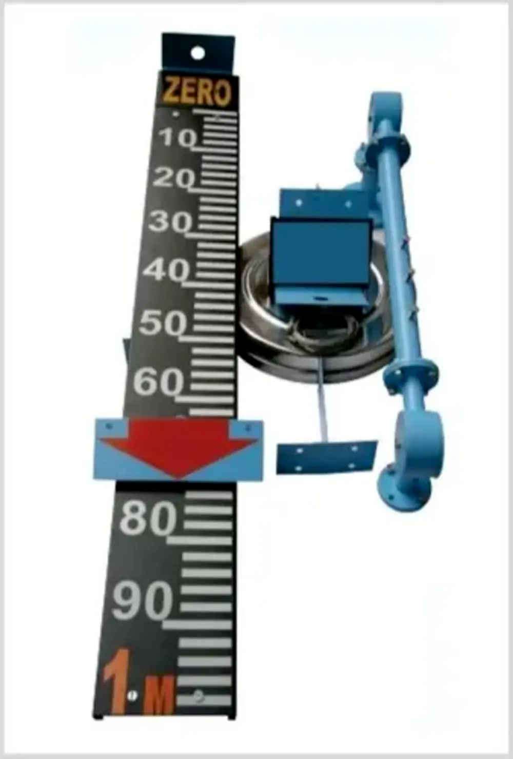 | Level Indicator The Float & Board Level Indicators consists of a float connected to a pointerthrough a rope via a set of pulleys. View product → |
Verify ratings, materials and hazardous-area safeguards
Confirm the complete level indicator for process vessels against the vessel’s maximum allowable working pressure, design temperature, vacuum condition and thermal-cycling range. Do not accept the transmitter-body rating as proof: the chamber, float or displacer, probe, seals, glass, remote-seal fill fluid, gaskets and isolation valves must withstand the same service.
Ask the supplier for these records before approval:
- A datasheet showing pressure, vacuum, minimum and maximum temperature, corrosion allowance, erosion limits and fugitive-emission performance for every wetted part.
- Material certificates and compatibility evidence for the process fluid, including concentration, water content, chlorides, solids and cleaning chemicals.
- The assembly drawing, nameplate data and flange or threaded-connection ratings; check them against the vessel design conditions, not normal operating values.
- The hazardous-area certificate, equipment protection method, gas or dust group, temperature class, ambient-temperature range, cable-gland requirements and intrinsic-safety entity parameters.
- The inspection, calibration and proof-test procedure, including isolation-valve testing and leak checks.
For a safety-critical alarm or shutdown, document the required safety integrity level and proof-test interval under the hazard analysis and IEC 61511 lifecycle. Do not count a normal transmitter and a high-high switch as independent protection layers when they share a chamber, impulse line, power supply, logic path or failure mechanism.
A local magnetic gauge needs no powered loop, but verify float density, magnet compatibility and freedom from coating or solids before trusting its indication.
Frequently asked questions
What measurement job should a level indicator perform?
Decide whether you need a continuous level value, a local reading or a point-level alarm. Level control also requires an output, controller and final control element.
How do pressure, temperature and fluid behaviour affect selection?
Match the instrument to vessel pressure and temperature, plus the fluid’s density, viscosity, corrosiveness, foaming, solids and tendency to coat surfaces.
What should you compare beyond measurement accuracy?
Compare visibility, maintenance access, calibration needs, spare parts, downtime and the total installed cost, including connections and commissioning.
What details belong in the purchase specification?
State the measuring range, process connections, mounting arrangement, wetted materials, pressure and temperature ratings, output requirements and hazardous-area safeguards.
Related products
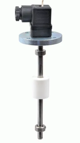
 | Level Switch Filpro offers most reliable, cost effective Side Mounted Level Switch for point level sensing. View product → |
 | Level Sensor Atex approved Float Level Transmitter : Over All Length: 300mm to 5000mm Input: 16V DC to 30V DC Output: 4-20mA / 0-10V DC Resolution: 5mm / 10mm... View product → |
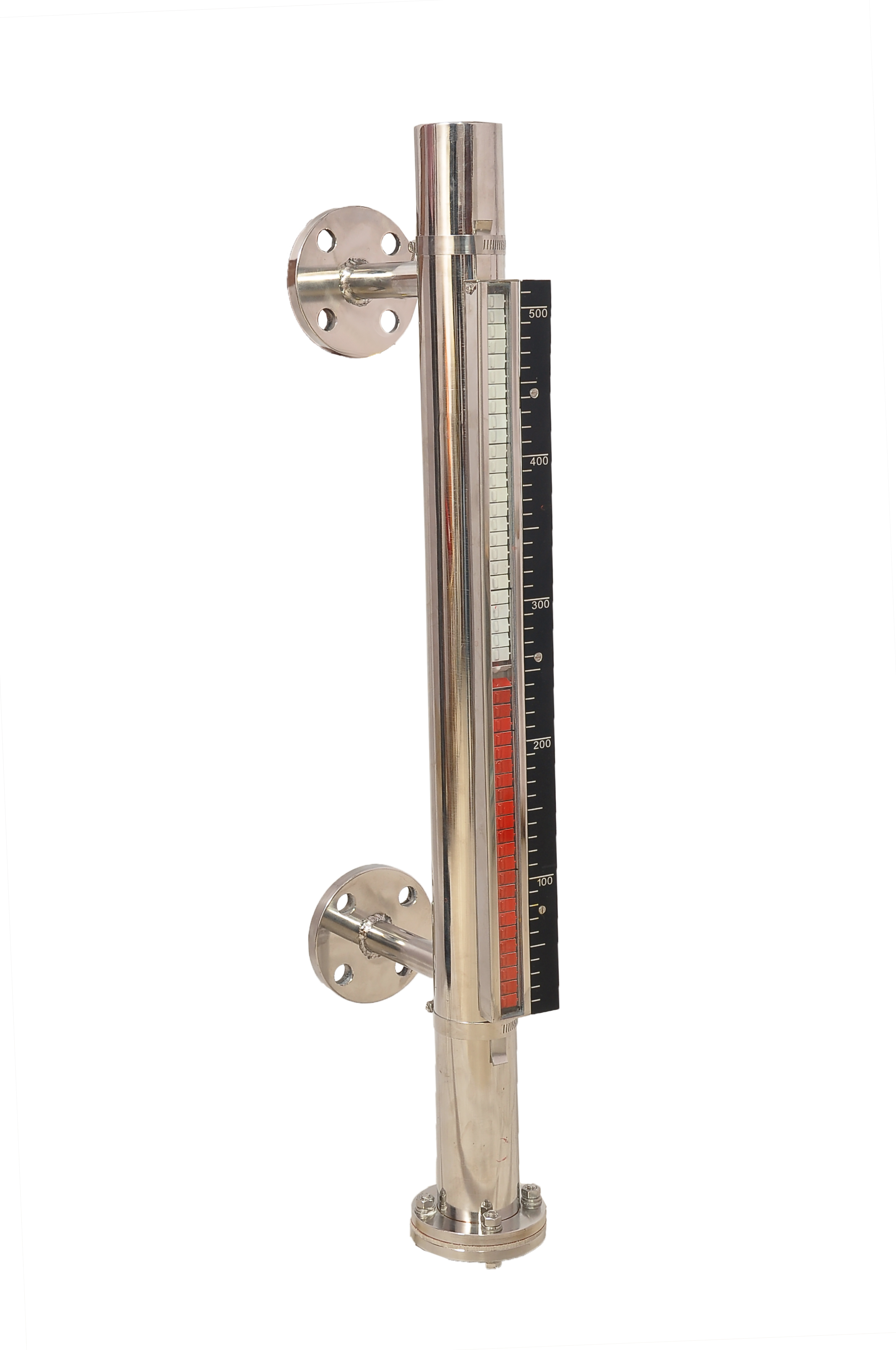 | Level Gauge FILPRO offers Magnetic Level Indicator provides clear, high clarity indication of liquid level. View product → |
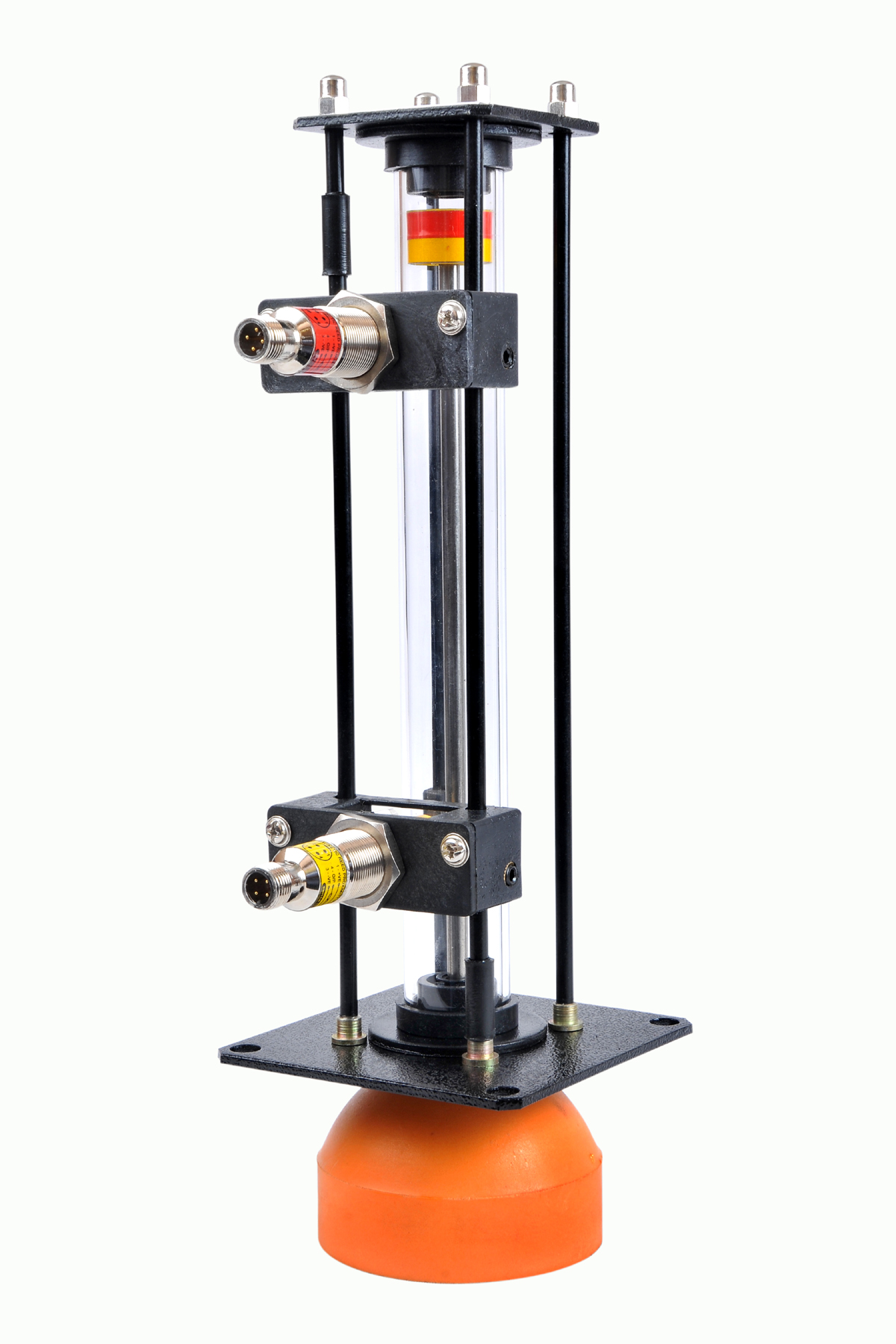 | Level Gauge Oil Level Indicator is designed to indicate the coolant and hydraulic oil level inside the tank with a visual indicator above the tank. View product → |