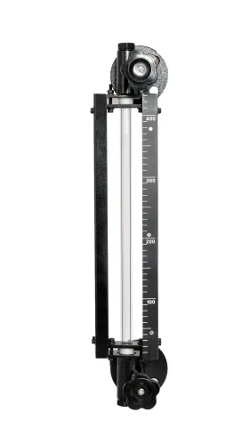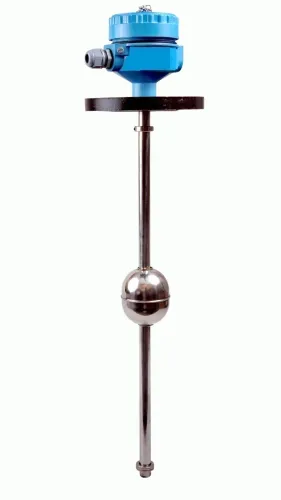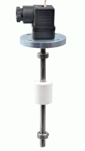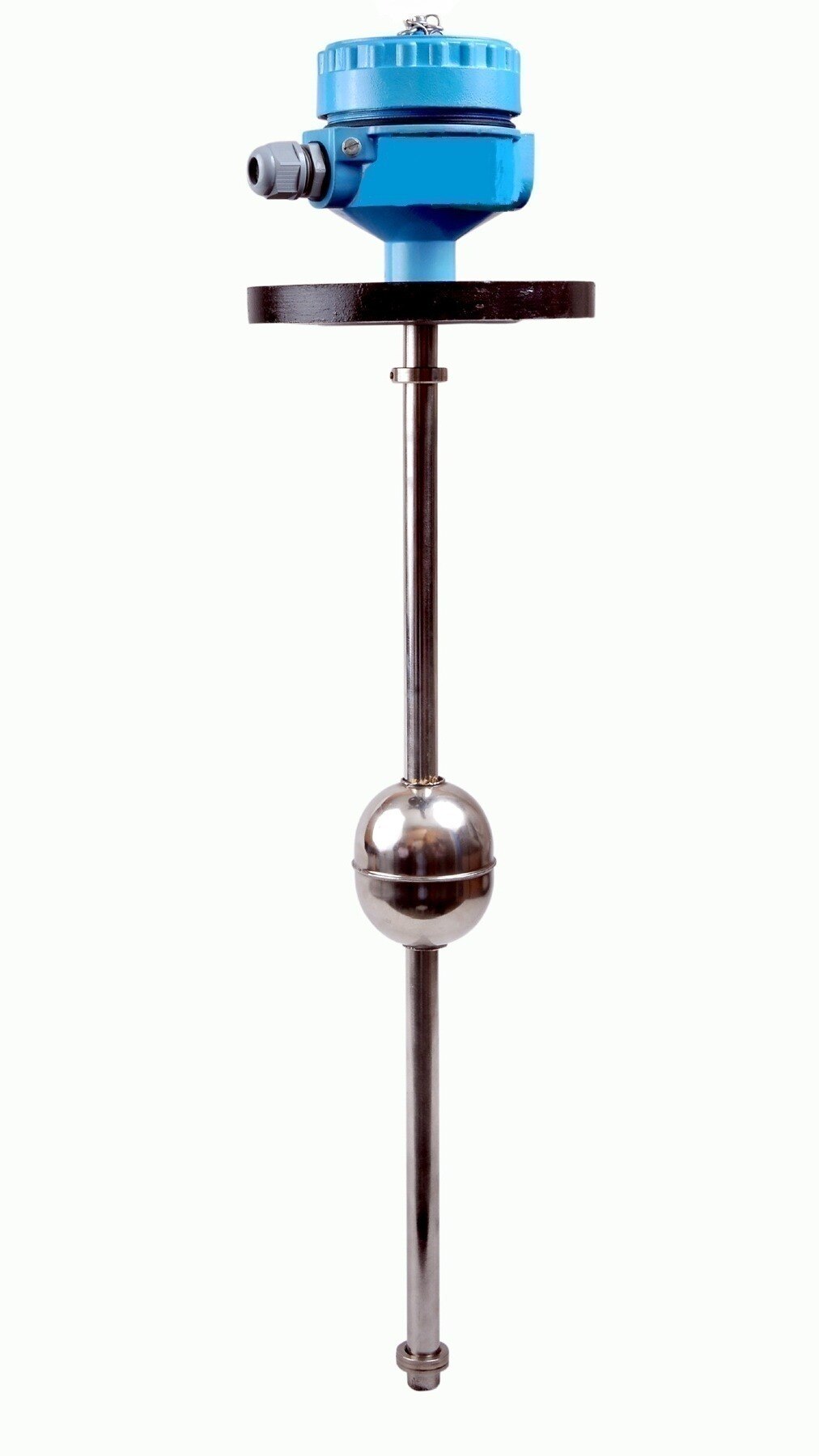
The right switch depends on more than the liquid height: tank geometry, fluid behaviour, process conditions, electrical logic and the consequence of a missed trip all affect the choice. By the end, you can narrow the technology, confirm that it fits the vessel and write a specification that distinguishes normal control from genuine overflow protection.
Key takeaways
- Choose point detection, pump control or continuous measurement first.
- Match the switch to tank shape and the required setpoint location.
- Check liquid properties, temperature, pressure and hazardous-area requirements.
- Specify alarm action, reset method, testing and acceptance criteria.
Start with the level function, not the switch body
Choose the function before the hardware: a point alarm, pump-control interlock, or continuous level measurement.
For an industrial level switch for tanks, the question is whether liquid has reached one defined height. It is not a substitute for a continuous level transmitter, which provides inventory, trend and rate-of-change data.
- Select a point alarm when you need a high, low or high-high warning at a fixed level. Place an independent high-high switch below the overflow when overfill protection is the objective.
- Select pump control when the switch must start or stop a pump at defined levels. Confirm that the switching cycle, motor load and consequences of a failed or chattering signal suit the pump-control scheme.
- Select continuous measurement when operators need tank inventory, level trends, rate-of-change information or proportional control. Add point switches for independent alarms or trips.
Test the complete installed function at the actual setpoint, or use a documented simulation. The test must cover the sensor, wiring, logic, alarm, interlock and final shutdown action; a bench test of the switch alone proves none of those links.
For an independent high-high trip, separate the switch from the normal transmitter, control loop, power supply, logic solver and final element where practicable. Specify failure action separately from normal switching: de-energize-to-trip exposes power loss or a broken circuit, but confirm the plant’s shutdown philosophy and spurious-trip consequences.
API 2350 treats overfill protection as a managed system, not a switch purchase.
Match the switch to tank geometry and setpoint location
Place the switch at the actual trip elevation, not at the most convenient nozzle. Set a high-high switch below the overflow by enough distance for incoming flow, pump stopping time, and operator response; keep it outside the inlet jet, agitator sweep, outlet vortex, roof dead zone, and bottom sediment zone.
| Tank geometry or condition | Suitable arrangement | Placement and access |
|---|---|---|
| Tall, narrow tank | Top-mounted vertical miniature switch | Use a rigid guide or probe; leave removal clearance above the roof |
| Turbulent filling or foaming liquid | Side-mounted point switch | Install below the fill inlet or use a permitted stilling arrangement |
| Deep tank or obstructed roof | Cable-float switch | Provide a clear vertical travel path and an accessible lifting point |
| Hygienic tank | Flush-mounted sanitary switch | Specify the connection, wetted material, surface finish, elastomer, and CIP/SIP rating together |
For a high level switch for tanks containing flammable liquid, match the enclosure, process seal, cable gland, barrier, temperature class, and electrical certification to the hazardous-area classification. A certificate on the switch alone does not validate an incompatible installation.
Use an independent high-high switch when the consequence is overflow: separate it from the normal transmitter, control loop, power supply, logic solver, and final element where practicable. Prove the complete function at the installed setpoint, including sensor, wiring, alarm, interlock, and shutdown; a bench test of the switch proves none of those final actions.
Check the liquid and process conditions before choosing a technology
Check the liquid’s physical properties and process limits before choosing a switch. A technology that works in clean water can fail in viscous, foaming, abrasive, or density-changing service.
| Option | Liquid or process condition | Decision |
|---|---|---|
| Vibrating fork | Clean liquid; low to medium viscosity; stable density | Strong default when the instrument’s minimum density, viscosity, pressure and temperature ratings fit |
| Float or displacer | Density stays within the buoyancy range; little sludge, wax or suspended solid | Use only when the float can move freely and the actual process density is known |
| Any point switch | Foam, bubbles or heavy agitation at the switching point | Reject that location; turbulence can cause repeated trips or missed switching |
| Conductivity-based switch | Liquid conductivity is reliably above the device threshold | Reject for non-conductive liquids or changing conductivity |
| Capacitance-based switch | Dielectric properties remain stable; coating is controlled | Reject when buildup changes the apparent switching point |
Confirm the instrument’s minimum and maximum temperature, pressure rating, process connection, and hazardous-area approval. A certificate alone is not enough: the cable gland, barrier, enclosure, temperature class and installation method must match the tank’s classification and gas or dust group.
Foam, entrained air and solids make mounting more important than tank size. Keep the sensing point out of the turbulent fill zone, or use a stilling arrangement where the process permits it.
For storage overfill protection, treat the switch as one part of the API 2350 system. Define operating limits, alarms, response procedures and proof testing; a high-level switch alone does not provide adequate protection.
Design high-level protection as a complete control function
Design a high-level switch for storage tanks as a complete control function, not as a component purchase. Use an alarm when an operator has enough time to investigate and stop filling manually. Use a pump-stop interlock when continued transfer could reach the overflow before a reliable operator response.
- Choose an alarm when the consequence is manageable and the response time is documented.
- Choose a pump stop when stopping the filling pump provides a fast, defined protective action.
- Choose an independent high-high trip when overflow could cause fire, contamination, environmental release, or dangerous pressure. Separate it from the normal transmitter and control path; use separate power, logic, and final shutdown elements where practicable.
Specify the failure action separately from the normal switching action. De-energize-to-trip exposes lost power, broken wiring, or an instrument fault as an alarm, but check the shutdown philosophy so spurious trips do not create a greater hazard.
Prove the whole function after installation at the actual setpoint, or use a documented simulation that exercises the complete signal path to shutdown. A bench test of the switch alone cannot prove the alarm or interlock works. API 2350 treats overfill protection as operating limits, alarms, response procedures, instrumentation, and proof testing.
A SIL claim also applies to the complete safety instrumented function under IEC 61511, not to the switch alone.
Turn the comparison into a purchase and acceptance specification
Specify the application in a purchase document, not just the phrase industrial level switch for tanks. Give the supplier the switching elevation, mounting orientation, tank drawing, liquid data, process temperature and pressure, turbulence, connection size, electrical load, normal and failed-state action, and the required alarm or interlock.
- State whether the device is a high level switch for tanks used for an independent alarm, pump stop, or overflow shutdown.
- Specify the contact arrangement, normal energised state, trip state, reset method, supply voltage, switching current, cable length, and enclosure rating.
- For flammable liquids, state the hazardous-area classification, gas or dust group, temperature class, barrier requirement, cable-gland type, process seal, and installation method. Check that these choices work together; an electrical certificate alone is not enough.
- For hygienic service, specify the process connection, wetted materials, elastomer, surface finish, cleanability, CIP/SIP temperature, and hygienic approval.
- State whether a continuous level transmitter is also required for inventory, trending, or rate-of-change information.
Ask for these details before ordering; Filpro Sensors Pvt Ltd can use them to distinguish a compact vertical arrangement from a side-mounted or float arrangement without guessing the service.
Accept the installation with a functional test at the actual setpoint, or a documented simulation that reproduces it. Record sensor operation, wiring continuity, logic response, alarm, interlock, and final shutdown action. A bench test of the switch alone proves none of those plant functions.
Record the failure action separately, and verify the complete overfill procedure and proof-test interval under API 2350.
Related products
 | Level Switch Filpro offers most reliable, cost effective Side Mounted Level Switch for point level sensing. View product → |
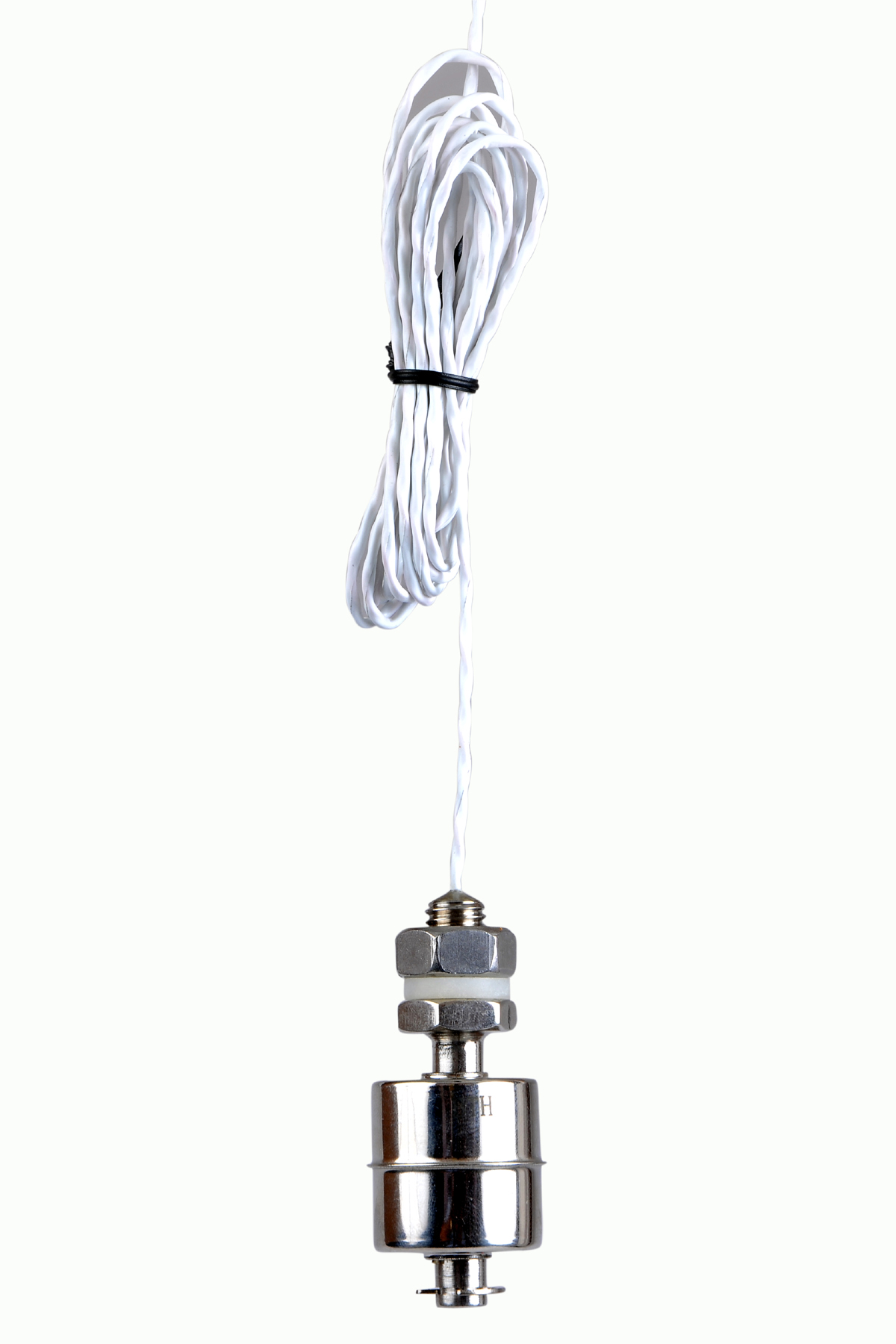 | Level Switch Stainless steel level switch - Miniature Stainless steel Miniature Level Switch is a compact construction, suitable for mounting vertically. View product → |
Frequently asked questions
How do you choose an industrial level switch for tanks?
Start with the required function: point-level alarm, pump-control interlock or continuous level measurement. Then match the device to tank geometry, setpoint location, liquid properties and process conditions.
What should you check before selecting a high level switch for tanks?
Check the liquid’s conductivity, viscosity, solids content, temperature and pressure. Confirm the tank material, nozzle or mounting arrangement, hazardous-area classification and required switching point.
How should a high level switch for storage tanks protect against overflow?
Define the complete control function: the high-level setpoint, alarm or shutdown action, fail-safe state, manual reset, independent power or signal path, proof-test method and response to sensor failure.
What belongs in a tank level switch purchase specification?
State the sensing technology, process connection, wetted materials, setpoint location, electrical output, supply voltage, enclosure or ingress rating, operating limits, approvals, documentation and factory or site acceptance tests.
Related products
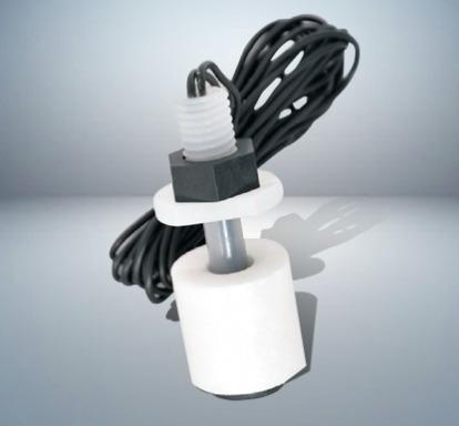 | Level Switch Plastic Miniature Level Switch is available in PP construction with PP Float Switching Voltage: 24V DC Switching current: 0.1A Mounting thread size:... View product → |
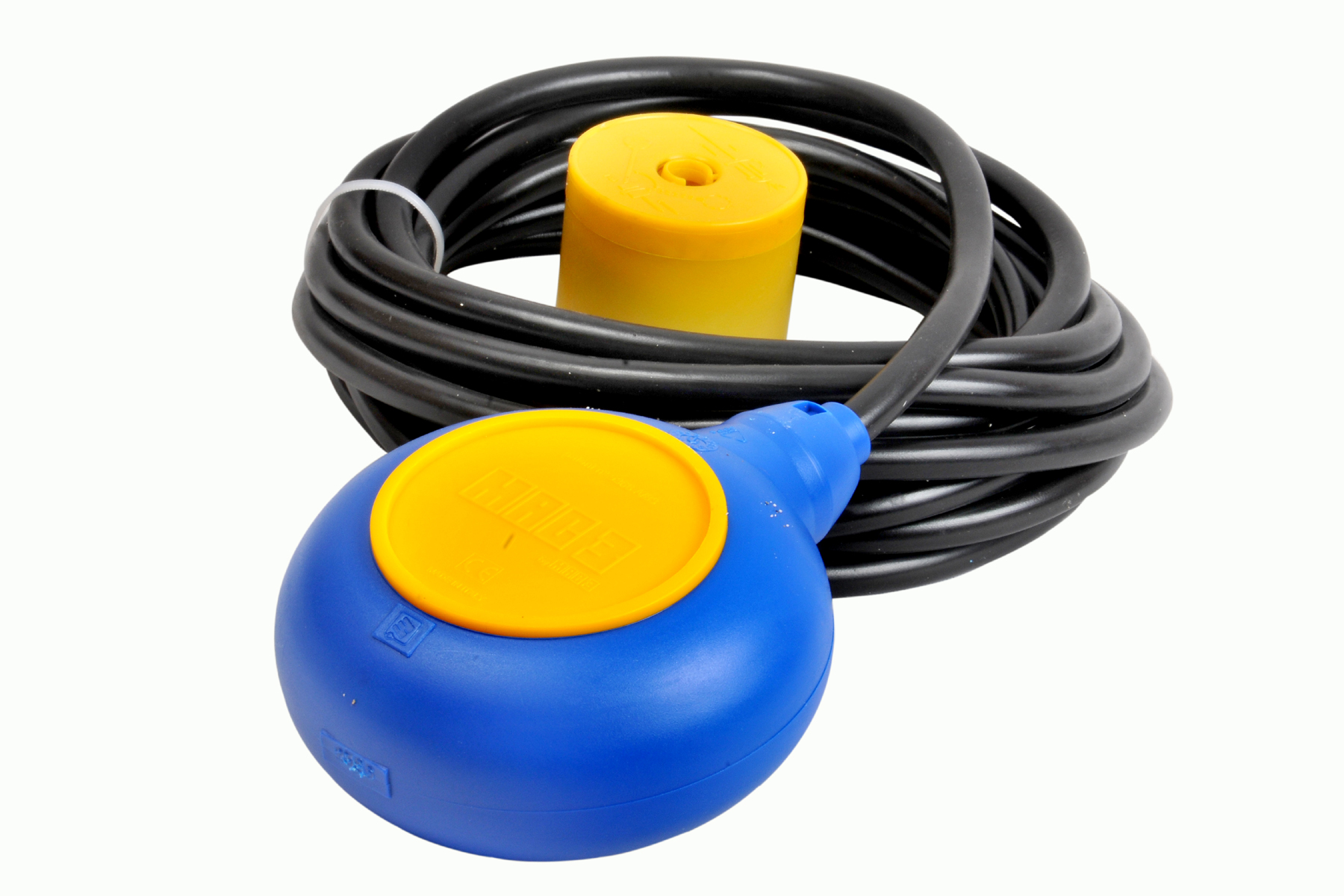 | Level Switch Cable Float Switch is mainly used for the automatic working of small pumps and cellar emptying pumps in liquids a little bit agitated. View product → |