A filling system must decide when to start, slow, stop, and safely inhibit the flow of liquid. By the end, you will be able to map the sensing device, controller logic, pump or valve output, setpoints, safeguards, and liquid properties to a dependable filling sequence.
Key takeaways
- Use point-level switches for simple start-and-stop filling.
- Set separate start, stop, alarm, and anti-cycling points.
- Choose continuous measurement when you need trend data or precise control.
- Match the sensor and actuator to the liquid’s properties.
How the controller turns a level reading into a fill command
A level controller for filling systems compares an input with a target, then commands an inlet valve, pump, or transfer device. A point-level switch supplies an on/off state: the controller starts at the low-level setpoint and stops at the high-level setpoint.
A continuous transmitter supplies a changing level, mass, or volume signal, allowing proportional or PID control.
A practical fill sequence is:
- When the low-level start point is reached, the controller checks the pump interlock and opens the inlet valve or starts the pump.
- During filling, it compares the measured value with the target. Separate start and stop setpoints create hysteresis, so surface movement does not switch the pump repeatedly.
- Before the high-level stop point, the controller may reduce flow or close the valve early to compensate for valve-closing time, pump rundown, line volume, and liquid momentum.
- At the stop point, it removes the fill command and waits for the level to fall below the restart point. A time delay adds further protection against rapid cycling.
- A high-high switch provides an independent overfill trip, while a manual override lets an authorised operator test or isolate the automatic command.
PID control suits continuous filling, but excessive integral action can overshoot a small vessel after shutdown. Sensor update rate, valve stroke time, pump-flow variation, and transmitter error also affect the final fill; ultrasonic readings can become unstable near the target when foam, vapour, or temperature gradients disturb the echo.
Choosing between point-level switches and continuous measurement
A point-level input tells the level controller for filling systems to start or stop at a threshold. A continuous transmitter supplies a changing signal for tighter control, trending, or a PID loop. Choose the device according to the tank geometry, liquid properties, accuracy required, and consequence of an overfill.
| Option | Signal | Choose it when | Main limitation |
|---|---|---|---|
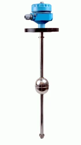
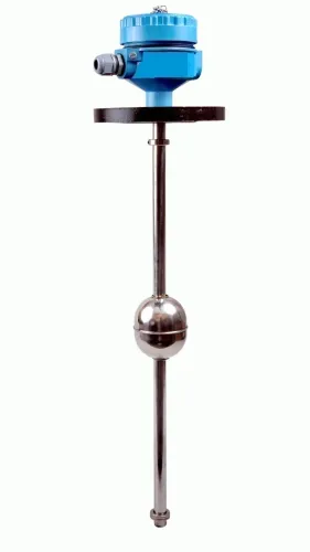
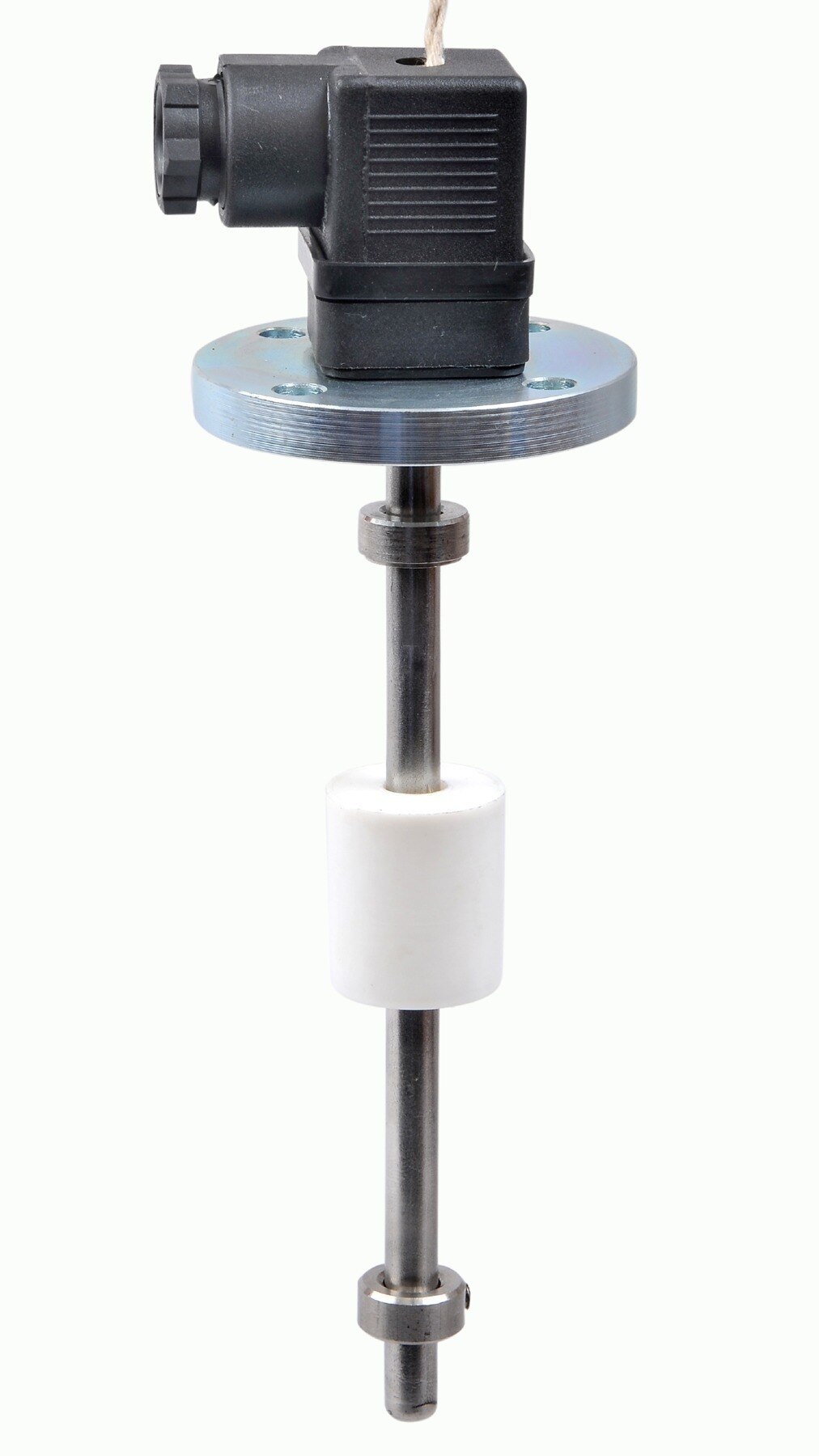
| Float switch | Discrete high or low contact | You need simple fill-and-stop control in a clean liquid with a stable surface | It can stick, foul, or cycle when turbulence moves the float |
| Side-mounted switch | Discrete contact at a fixed elevation | A top entry is unavailable, or you need a compact high-level or low-level alarm | The mounting nozzle must suit the switch, and the vessel wall needs a clear installation point |
| Hydrostatic transmitter | Continuous pressure signal | The tank is closed, the liquid density is known, and you need continuous level control | A density change, plugged impulse path, or pressure from an agitator can shift the reading |
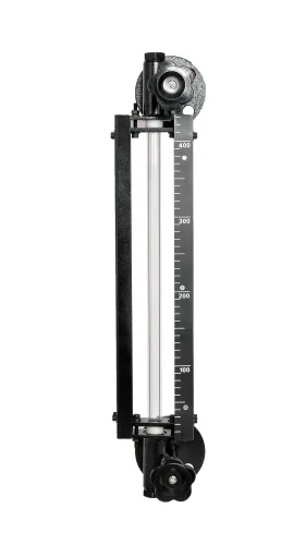
| Float transmitter | Continuous position signal | You need a simple continuous reading in a calm tank with a guided float | Mechanical wear, guide friction, and foam can distort the level signal |
| Capacitance transmitter | Continuous electrical signal | The liquid has stable dielectric properties and the probe can remain clean | Product coating, changing conductivity, or a non-conductive vessel can alter calibration |
Use separate high-high protection for a serious overfill hazard; do not rely on the normal transmitter or software alone. In hygienic service, select fittings and probe surfaces that drain fully and withstand the cleaning cycle. Add hysteresis or time delay when a switch chatters around its setpoint.
Setting start, stop, alarm, and anti-cycling points
A level controller for filling systems must convert the required volume into a level that fits the tank’s geometry. In a vertical cylindrical tank, a small height change represents less volume than the same change in a wide tank; in a horizontal or irregular vessel, the volume-to-level relationship changes throughout the fill.
Set start and stop points from usable volume, not from a percentage copied from another tank.
The stop point must allow for liquid that arrives after the command. Include valve closing time, pump rundown, line volume and inlet momentum when estimating residual flow. If the target is 500 litres and the system delivers 8 litres after shutdown, set the normal cutoff near 492 litres, then verify the result with measured batches.
Hysteresis separates the restart level from the stop level. A wider differential prevents a turbulent surface or small leak from repeatedly starting the pump, but it reduces the available working volume. A time delay rejects brief level excursions; excessive delay lets the tank pass the stop point before the actuator responds.
- Set the low start point above the pump’s minimum submergence and below the required operating reserve.
- Set the high stop point below the usable-volume limit, leaving room for residual flow and foam.
- Place the high-high alarm or independent overfill trip above the normal stop and below the tank’s safe maximum; do not use it as the routine control point.
- Test points during the fastest and slowest inlet conditions, including the final slow-fill or top-off phase.
- If integral action causes overshoot, reduce it or add cutoff compensation; a slow storage-tank setting can oscillate in a small vessel.
Making the filling system fail safely
Make the filling system fail safely by stopping addition when the controller cannot prove that filling is safe. A level controller for filling systems needs a defined response for each instrument and power fault, not one generic “fault” state.
- Empty receiving tank: permit filling only when the source tank, pump, and downstream path are available. If an empty source tank causes lost suction, stop the pump on the low-low source-level or suction-pressure interlock to prevent dry running.
- Lost pump suction: close the inlet valve or de-energise the pump, then require a deliberate reset after suction returns. Do not let automatic restart damage the pump or introduce air into the line.
- Broken sensor cable: treat an open circuit, invalid current signal, or failed communication as a bad measurement. Stop filling and raise a fault; do not interpret the failure as low level.
- Power failure: select a spring-return valve or de-energise-to-trip motor circuit that leaves the process in the safer state. On restoration, block automatic restart until level, valve position, and pump permissives are checked.
- Implausible reading: alarm and inhibit filling when the signal jumps beyond the configured rate, disagrees with an independent switch, or exceeds the transmitter range. A high-high switch should independently stop the pump or close the inlet.
- Manual intervention: use a keyed hand-off-auto selector, display the active mode, retain high-high protection, and require confirmation before returning to automatic control. Limit hand filling with a timer or operator-held command.
Matching the measurement and actuator to the liquid
A level controller for filling systems must match the measurement to the liquid and the required batch accuracy. Viscous or foaming liquids can delay or disturb a surface reading; changing density shifts hydrostatic measurements.
Final quantity also depends on sensor update rate, valve repeatability, actuator stroke time, pump-flow variation, loop tuning and liquid delivered after the stop command.
| Final control element | What it changes | When it fits |
|---|---|---|
| Inlet valve | Gives predictable throttling and rapid cutoff when correctly sized; closing time still creates residual flow. | Use for continuous PID control or precise top-off where supply pressure is stable. |
| Pump | Transfers liquid without a separate inlet valve, but rundown, variable flow and line momentum affect the final quantity. | Use when the pump is the natural transfer device; add early cutoff or a slower top-off speed for batch filling. |
Specify cutoff compensation from measured overrun: stop early by a calibrated volume, or switch from fast fill to slow fill before the target. Tune PID using the actual valve or pump response; aggressive gains cause hunting, while slow gains leave long settling times.
Hygienic service makes the measurement point part of the cleanability design. Reject fittings with crevices, undrainable dead legs, rough product-contact surfaces or materials that cannot withstand the cleaning temperature and chemicals.
When evaluating a hydrostatic transmitter from Filpro Sensors Pvt Ltd, check diaphragm compatibility and density range rather than treating its stated accuracy as the batch accuracy.
For hazardous areas, approve the complete protection concept:
- Match the transmitter, controller, switches, solenoids and barriers to the area classification, gas or dust group and temperature class.
- Verify wiring, isolation and maintenance procedures; suitable ratings on one instrument do not make the installation safe.
- Define the final element’s failure position: a spring-return valve may fail closed, while a pump needs a de-energize-to-trip circuit when continued filling creates the greater hazard.
Related products
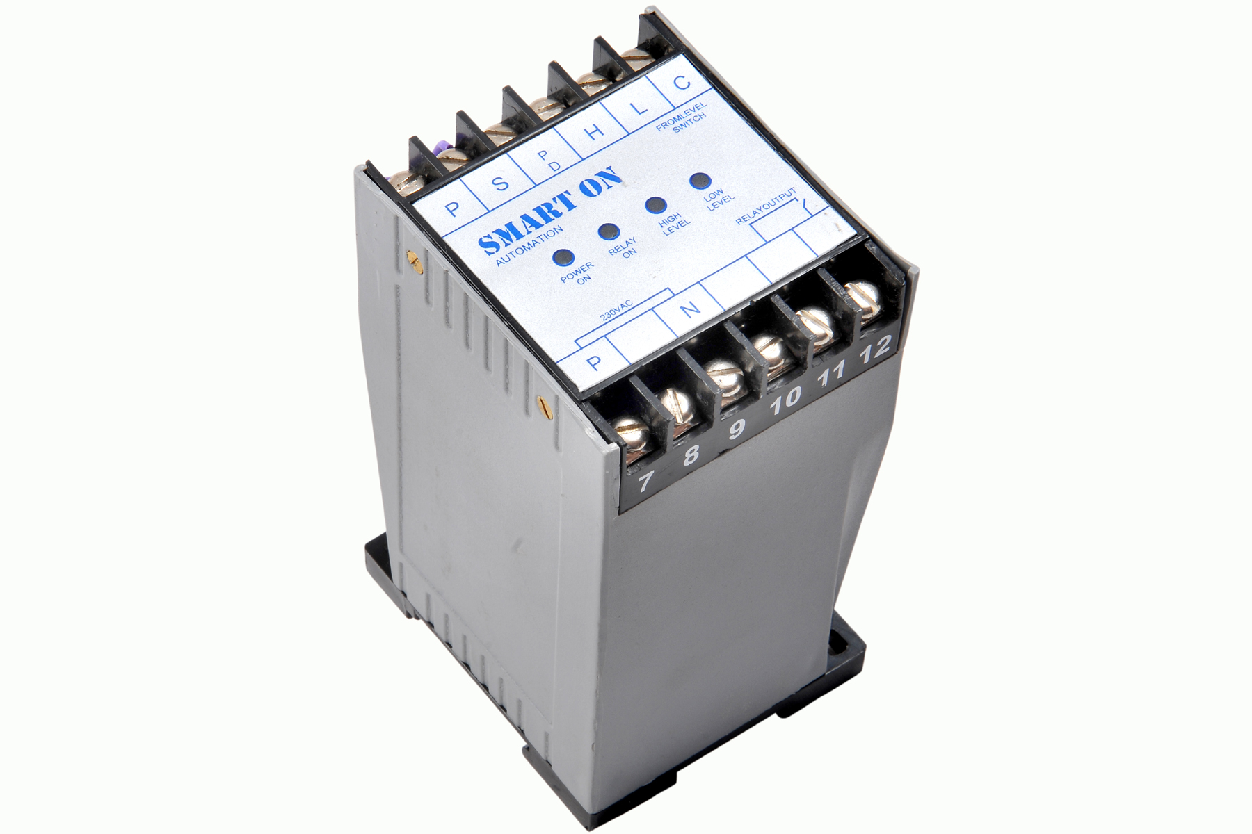 | Controller Filpro Sensors Pvt Ltd manufactures industrial Level Controller (Smart On) to automatically start & stop the pump. View product → |
 | Level Switch Filpro offers most reliable, cost effective Side Mounted Level Switch for point level sensing. View product → |
Frequently asked questions
How does a level controller turn a reading into a fill command?
The controller compares the measured level with configured setpoints, then starts or stops an inlet valve, pump, or transfer device.
When should you use a point-level switch instead of continuous measurement?
Use a point-level switch for straightforward on/off filling at defined levels. Choose continuous measurement when you need level trends, tighter control, or multiple operating thresholds.
Which level points should you set in a filling system?
Set a start point, stop point, high-level alarm, and low-level alarm. Add an anti-cycling band or time delay to prevent repeated starts and stops.
How can a filling system fail safely?
Define the response to sensor failure, loss of power, broken wiring, and controller faults. Use a fail-safe valve or pump state and an independent high-level shutdown where overflow has serious consequences.
How do you match measurement equipment to the liquid?
Check viscosity, conductivity, temperature, pressure, foam, corrosiveness, vapour, and solids before selecting the sensor. Confirm that the valve or pump suits the required flow and liquid compatibility.