A conductive probe does not calculate tank height by measuring water pressure or sound. It detects whether water has completed an electrical path between an energized electrode and a reference, then sends a switching signal to a controller. By the end, you will know how to position and wire the electrodes, diagnose unreliable switching, and decide when another level technology is the better fit.
Key takeaways
- Water must bridge the sensing and reference electrodes to complete the circuit.
- Use separate electrodes for each level point and a reliable reference path.
- Ground the controller and limit electrode excitation to prevent unsafe installation.
- Check water conductivity, tank material, fouling, and switching points before specifying.
How water completes the sensing circuit
A conductive level sensor for water switches when water bridges an energized sensing electrode and a reference electrode. The water completes the electrical path, allowing a small current to flow; the controller detects that current or the resulting impedance and changes its output. It detects contact at a point, not liquid height directly.
The sensing electrode’s end establishes the switching elevation. In a metal tank, the tank wall can serve as the reference when it is electrically bonded to the controller. In a plastic tank, install a separate reference electrode, with enough spacing to prevent accidental contact or coating-related bridging.
| Configuration | What it detects | Typical use |
|---|---|---|
| Single electrode and reference | One switching point | High-level alarm, low-level alarm, or pump control |
| Several electrodes and reference | Separate switching points | Low, high, and overfill control in one tank |
Ordinary water contains dissolved ions, so it usually conducts enough current for reliable switching. Deionized or distilled water can produce weak or inconsistent detection, especially when its conductivity changes near the sensor threshold.
Keep probes away from inlets, spray balls, agitators, and turbulent returns. Foam, condensation, or wet deposits can bridge the electrodes early; switching delay or hysteresis helps prevent a false alarm. The actual alarm or pump setpoint also depends on probe position, tank geometry, and control logic.
How probe count, spacing and tank material set the level points
Arrange a single electrode at the required switching elevation and use the tank or a separate reference electrode to complete the reference path. A short probe suits a low-level or dry-run point; a longer probe reaches a high-level alarm point. Probe length sets elevation, not an exact volume.
| Tank type | Single-point arrangement | Multipoint arrangement |
|---|---|---|
| Metal tank | Use one insulated sensing probe with a reliably bonded, grounded vessel as reference. Add a dedicated reference electrode when paint, liners, corrosion or uncertain bonding separates the liquid from the metal. | Install separate insulated probes at low, high and overfill elevations, with adequate clearance between tips. Use the tank as reference only after checking bonding and grounding. |
| Plastic tank | Install a sensing probe and a dedicated reference electrode that reaches the same liquid zone. A plastic wall cannot provide the return path. | Use one reference electrode plus individually insulated probes at each switching elevation. Keep every tip clear of fittings and the tank bottom. |
Leave space between electrodes to prevent mineral scale, biological growth or conductive residue from creating a false bridge. Keep probes away from fill streams, agitators and turbulent outlets, where splashing can cause rapid switching.
For conductive level sensor applications such as pump control, dosing and alarms, label each probe by function and test the actual switching point after installation. Adjust probe positions rather than assuming a marked tank volume matches the control level.
How to install and excite conductive electrodes safely
Use the controller’s specified alternating or polarity-reversing excitation, not a steady DC supply. Wire the energized electrode and reference electrode to the matching controller terminals, and follow the manufacturer’s cable length, shield, and grounding instructions. In a hazardous area, use the complete certified intrinsically safe circuit, including the associated apparatus and approved wiring method.
- Mount the probe where foam, spray, condensation, and wet deposits cannot bridge the electrodes. Keep it away from an inlet, agitator, spray ball, and turbulent return.
- Set switching delay or hysteresis when splashing could create brief level signals. Without it, the output may chatter or trip before the bulk liquid reaches the set point.
- Choose electrode material and insulation for the liquid’s chemistry and temperature. Leave the sensing tip exposed, insulate the stem where a coating could create a leakage path, and provide access for cleaning.
- Check the sensor’s specified minimum conductivity against the actual water. Distilled, deionized, or purified water can fall below the switching threshold even when tap water works.
- Route the cable away from power conductors and inspect the probe for scale, corrosion products, biological growth, and process residue. Deposits can either block detection or create a false level signal.
How to distinguish true water contact from a false signal
A false level signal usually comes from an unintended conductive path, not a failed electrode. Troubleshoot the liquid path, insulation, cable and reference connection in that order.
1. Record the false state, then stop inflow, agitation and spray. If the signal disappears after foam, condensation or turbulent return settles, add physical separation, switching delay or hysteresis rather than replacing the probe.
2. Isolate power and inspect each electrode, holder and cable entry. Remove mineral scale, corrosion products, biological growth and process residue; deposits can insulate a probe or bridge adjacent electrodes.
3. Dry the probe assembly and mounting hardware completely. Wet insulation, condensation inside a terminal enclosure, or contaminated cable glands can connect electrodes outside the tank.
4. Disconnect the field cables at the controller and test each conductor for leakage to other conductors, cable shield and tank earth. Use an insulation test method within the cable and controller manufacturer’s limits.
5. Check that the reference electrode or grounded tank has a clean, low-resistance connection. A loose bond, painted contact surface or unintended ground can make the controller interpret leakage as water.
6. Test the controller with clean water at the intended electrode and with the vessel empty. If the input remains active with field wiring disconnected, investigate the controller or its scan circuit; do not apply steady DC to the electrodes.
Which water-level jobs suit conductive sensing
A conductive level sensor for water suits on/off decisions rather than continuous volume measurement. It detects a defined water contact point, making it effective for a high-level alarm, low-level dry-run protection, or automatic pump start and stop. Ordinary tap water usually works; distilled, deionized, or highly purified water may not provide enough current.
Common conductive level sensor applications include:
- Tank high-level and low-level alarms
- Pump start/stop control
- Dry-run protection
- Dosing-tank control
- Boiler and water-treatment equipment
- Sump and leak detection
| Option | Best fit | Main limitation |
|---|---|---|
| Conductive | Water point alarms and pump control | Needs sufficient, stable conductivity |
| Float | Simple single-point switching | Moving parts and limited positioning |
| Hydrostatic | Continuous level in deep tanks | Pressure depends on liquid density |
| Ultrasonic | Non-contact continuous measurement | Foam, vapour, turbulence, and obstructions can disturb echoes |
| Capacitance | Continuous or point sensing across more liquid types | Requires careful setup for coating and changing dielectric conditions |
A conductive level sensor for water is the wrong choice when you need an exact volume, the liquid conductivity crosses the switching threshold, or the tank contains oil or solvent.
When comparing options from Filpro Sensors Pvt Ltd, ask for the minimum conductivity, switching hysteresis, and whether the stated setpoint is the probe elevation or the actual pump-control level.
Related product
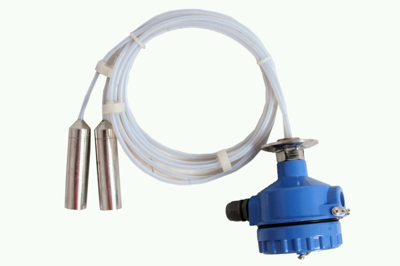 | Level Transmitter can be used for conductive as well as non conductive liquids. View product → |
What to check before specifying a conductive sensor
Before purchase, define the switching task and verify the liquid at its actual operating temperature and concentration. A sensor that works in process water may switch unreliably in deionized water, condensate, or a changed formulation.
| Check | Confirm | Why it matters |
|---|---|---|
| Conductivity | Minimum conductivity at the coldest, cleanest condition | Low conductivity can prevent a reliable switch |
| Level | Electrode elevation, tank geometry, movement, and control setpoint | Probe length sets a point, not an exact volume |
| Materials | Electrode, insulation, tank, gasket, and process-fitting compatibility | Corrosion or deposits can cause missed or false signals |
| Process | Inlet, agitator, spray ball, turbulence, foam, condensation, and temperature | Wetting near the probe can trigger early; add separation, delay, or hysteresis |
| Controller | Supply voltage, input type, switching current, relay capacity, and fail-safe behaviour | An incompatible controller can damage the probe or leave a pump unprotected |
| Maintenance | Scale, biological growth, residue, inspection frequency, cleaning method, and access | Fouling can insulate the electrode or create a leakage path |
| Alarm and control | High-level, low-level, dry-run, pump start/stop, dosing, leak, or sump duty; latching and reset rules | The wrong relay logic can overflow a tank or run a pump dry |
| Hazardous area | Area classification, certified probe, intrinsically safe barrier or associated apparatus, cable, and installation method | Water does not make a circuit safe for a hazardous location |
Commission with the real liquid, then test every alarm, delay, reset, and loss-of-signal response. Record the measured switching point.
Frequently asked questions
How does a conductive level sensor detect water?
Water bridges an energized sensing electrode and a reference electrode, completing an electrical path that the controller detects as level contact.
How do probe count, spacing, and tank material affect level detection?
Each probe marks a switching point, probe spacing sets the level difference, and a conductive tank can provide the reference path when correctly bonded.
How should you install and excite conductive electrodes safely?
Mount electrodes securely, keep wiring insulated, bond conductive tanks correctly, and use the controller’s specified low-energy excitation rather than an improvised supply.
How can you distinguish true water contact from a false signal?
Check water conductivity, electrode fouling, cable insulation, tank grounding, condensation, and whether the signal disappears when the probe is dry.
Which water-level jobs suit conductive sensing?
Conductive sensing suits point-level detection in conductive, non-foaming water for functions such as pump control, overflow protection, and low-level alarms.