A quotation for a float instrument can cover only the sensing assembly, while the tank still needs a power supply, cable, receiving device and correctly sized mounting connection. By the end, you will be able to identify each package component, verify the measuring range and installation fit, compare signal options, and check that the delivery documents and accessories match your tank.
Key takeaways
- Match the float range to the tank’s usable level, not its total height.
- Confirm process connection, cable entry, output signal and supply voltage before ordering.
- Scale the transmitter at empty and full levels during commissioning.
- Request material certificates, calibration records and hazardous-area documents when required.
What the float transmitter package actually contains
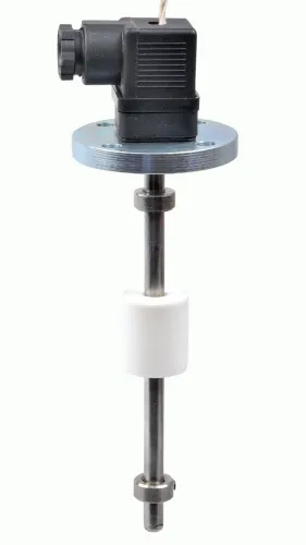
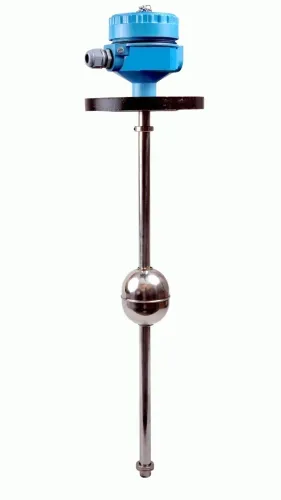
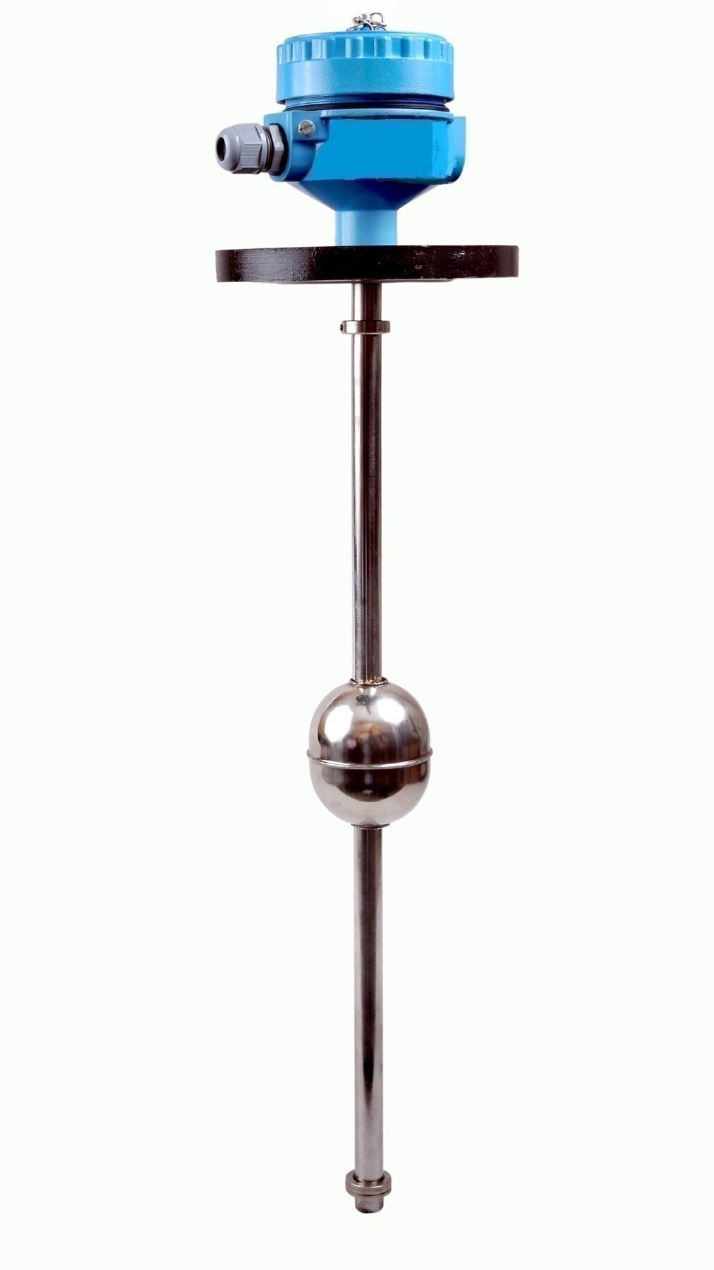
A standard package contains the float, probe or guide tube, magnetic coupling, reed-chain, Hall element or magnetostrictive position element, transmitter head, process connection, cable entry, connector, brackets and fasteners. The float follows the liquid along the probe; its magnetic position is detected through the tube and converted into a usable signal.
Power supply, signal cable, PLC input, display, data logger and isolation barrier require a separate quotation unless listed.
| Type | Signal or indication | What you receive |
|---|---|---|
| Float level sensor | Switch, resistance, pulse or raw position | Sensing element without guaranteed 4–20 mA conditioning |
| Float level transmitter | 4–20 mA, 0–10 V, HART or Modbus | Conditioned continuous measurement from the sensing assembly |
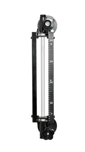
| Float-and-board mechanical indicator | Local visual level only | Board and float indication without continuous electrical output |
Tank float transmitter options include a local display, alarm switches, temperature sensing and dual outputs. Specify switch positions and hysteresis for multi-point alarms, not just the number of points.
At the bottom or top, the float reaches its mechanical travel limit and the output stops at the configured zero or full-scale value. If sludge, crystallisation, viscosity, turbulence or an internal fitting blocks it, the reading can remain fixed or become false.
A stilling well, guide cage or bypass chamber is a separate design item; so are mounting flanges, special brackets and fasteners when they are not included in the quotation.
How to confirm the range, mounting and specifications
Confirm the fit from a tank drawing, not tank height alone. Record total tank height, usable measuring length, top-entry or side-entry mounting, nozzle diameter, flange standard or thread size, insertion depth, roof clearance, float diameter and wall clearance. Mark coils, ladders, mixers, inlet streams and the route needed to remove the float.
A 3,000 mm probe does not necessarily provide a 3,000 mm measurement. Top and bottom inactive zones, float travel limits, process connections and electrical dead zones reduce the calibrated span. Require the quotation to state the reference datum and the exact 0% and 100% points.
| Dimension | Meaning | Ordering check |
|---|---|---|
| Total tank height | Physical bottom-to-roof distance | Do not use it as the measuring range |
| Probe length | Overall stem or guide-tube length | Confirm insertion depth and inactive ends |
| Calibrated span | Distance between configured 0% and 100% levels | Match it to the required usable level |
Use this float level transmitter specifications checklist:
- Supply voltage; two-wire, three-wire or four-wire connection; output wiring; load resistance; HART or digital protocol; accuracy, repeatability, resolution and response time.
- Ambient and process-temperature limits; pressure rating; enclosure rating; wetted materials; cable length; gland or connector; and fault-current behaviour, including upscale or downscale failure.
- State whether the output represents level or volume. Volume requires a tank strapping table or control-system linearization, especially in horizontal or irregular tanks.
Ask the supplier to list every item in the float transmitter package contents, including exclusions such as cable, display, barrier, stilling well or mounting hardware.
How to wire, scale and commission the output
Check the float transmitter package contents and wiring diagram before energising. Confirm the power-supply voltage, input type, output mode, minimum loop voltage, maximum loop resistance and whether an isolation barrier is required.
- For a two-wire 4–20 mA loop, connect supply positive to transmitter positive, transmitter negative to PLC AI+, display, data logger or fuel-controller input, then return the input negative to supply negative. Observe polarity. Keep total loop resistance below the transmitter’s stated maximum and leave enough supply voltage after cable and input drops.
- For a three-wire or four-wire 0–10 V DC output, connect the supply conductors, signal to AI+, and supply or signal common to AI−. The receiving input must accept 0–10 V and share the transmitter’s common reference.
- Bond the enclosure as specified. Terminate the cable shield at one end only, usually the control-panel end, and route the cable separately from motor and variable-frequency-drive wiring. Use galvanic isolation when the manufacturer, hazardous-area installation or earth-loop risk requires it.
Scale 4 mA to the configured zero level and 20 mA to the configured full-scale level. Scale 0–10 V to the same span and common reference.
- Record empty, known intermediate and full levels.
- Simulate each output and check PLC indication, alarms and recorder values.
- Document as-found and as-left readings, scaling, polarity and alarm settings.
Constant 4 mA: check wiring, supply and a blocked float. Constant 20 mA: check polarity, scaling and fault-current settings. Zero voltage: check supply, common and the input card. Noise: check shielding, segregation and earth loops; replace a failed input card.
When materials, hazardous areas and tank conditions change the choice
Do not choose a float from the label “fuel” or “chemical.” Buoyancy depends on liquid density, viscosity and surface tension, so ask the supplier for the minimum operating density and the float design. Check the liquid, vapour space, seals, float, stem, process connection and temperature against chemical-compatibility data.
Verify SS 304, SS 316, SS 316L, titanium and elastomer grades; none is an automatic recommendation.
| Instrument | Main limitation | Better fit |
|---|---|---|
| Float | Fouling, sludge, crystallisation, vibration and contact with the liquid | Clean, accessible tanks with guided float travel |
| Hydrostatic | Density changes alter the pressure-to-level calculation | Stable-density liquids |
| Ultrasonic | Foam, vapour, turbulence and obstructions can disturb echoes | Non-contact measurement with a clear acoustic path |
| Radar | Obstructions, turbulence and unsuitable vapour conditions need antenna and setup checks | Non-contact measurement where the application suits radar |
For ATEX equipment, match the site zone, equipment category, gas or dust group, temperature class and protection marking to the certificate. Request the certificate number, EU declaration of conformity, installation instructions, and any intrinsic-safety or barrier requirements.
A float is the wrong choice for sludge, crystallisation, aggressive vapours, restricted access, severe vibration, frequent fouling or any application requiring non-contact measurement.
- Float movement checks and cleaning
- Seal and gland inspection
- Zero and full-level verification
- Output simulation
- Replacement of worn moving parts
What to require at delivery and from a Mumbai supplier
At delivery, compare the quotation with the crate, not the catalogue. For a float level transmitter and float level sensor package in Mumbai, require this scope in writing:
| Item | Standard package | Optional or confirm separately |
|---|---|---|
| Float and probe | Specified length, float, guide tube, transmitter head | Custom probe length, dual output or temperature sensor |
| Connection and mounting | Flange or thread, cable entry, brackets and fasteners | Special flange, guide cage, stilling well or bypass chamber |
| Signal and indication | Chosen 4–20 mA, 0–10 V, HART or Modbus output | Local display, alarms, data logger, isolation barrier and signal cable |
| Materials and calibration | Stated wetted materials and calibration points | Special alloys, extra test points and non-standard calibration |
| Delivery | Stated lead time and dispatch scope | Site survey, installation and commissioning |
Check the product label, serial number, packing list, wiring diagram, dimensional drawing, installation manual, calibration or test record, material statement, certificate of conformity, warranty terms and ATEX documents where applicable.
Avoid these ordering errors:
- Confusing tank height with usable calibrated range
- Choosing an output that the PLC cannot accept
- Omitting the power supply
- Ignoring coils, mixers, ladders or inlet streams
- Specifying incompatible wetted materials
- Ordering ATEX equipment without confirming the site classification
Ask a float sensor transmitter supplier in Mumbai for drawing review, custom-length fabrication, technical drawings, calibration support, country of manufacture, loop checking, installation, troubleshooting, spare parts and service coverage. Evaluate Filpro Sensors Pvt Ltd against those deliverables, documented dispatch scope and response terms—not catalogue claims alone.
Related products
 | Level Transmitter Float Level Transmitters Are Ideal For Continuous Level Monitoring In Water, Diesel, Chemical And Oils For Accurate Level Measurement. View product → |
 | Level Sensor Atex approved Float Level Transmitter : Over All Length: 300mm to 5000mm Input: 16V DC to 30V DC Output: 4-20mA / 0-10V DC Resolution: 5mm / 10mm... View product → |
Frequently asked questions
What comes in a float level transmitter package?
A package can include the float, probe or guide tube, magnetic coupling, sensing element, transmitter head, process connection, cable entry, connector, mounting brackets and fasteners. Confirm the exact bill of materials because accessories vary by model.
Which float level transmitter specifications should you confirm?
Check the measurement range, float dimensions and density, probe length, process connection size, enclosure rating, output signal, supply voltage, electrical connection, wetted materials and operating temperature. Confirm that the range covers the tank’s usable level.
How do you wire and commission a float level transmitter?
Verify the supply and output terminals against the wiring diagram, connect the signal cable with the required shielding and grounding, then set the empty and full reference points. Confirm the displayed or transmitted value against a measured tank level before placing the system in service.
When do tank conditions change the transmitter choice?
Choose different materials or construction when the liquid is corrosive, abrasive, viscous, hot, pressurised or contaminated with solids. Hazardous areas also require the specified protection method, certified cable glands and compatible installation practices.
What should you require from a Mumbai float sensor transmitter supplier?
Request a datasheet, dimensional drawing, wiring diagram, calibration record, material details, inspection documents and any hazardous-area certificates. Confirm delivery includes the ordered mounting hardware, connector, cable entry and other listed accessories.