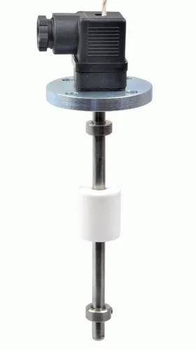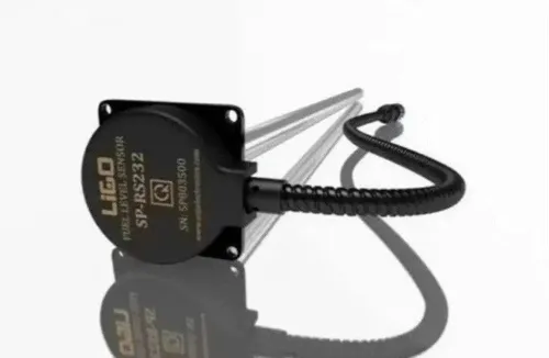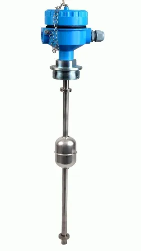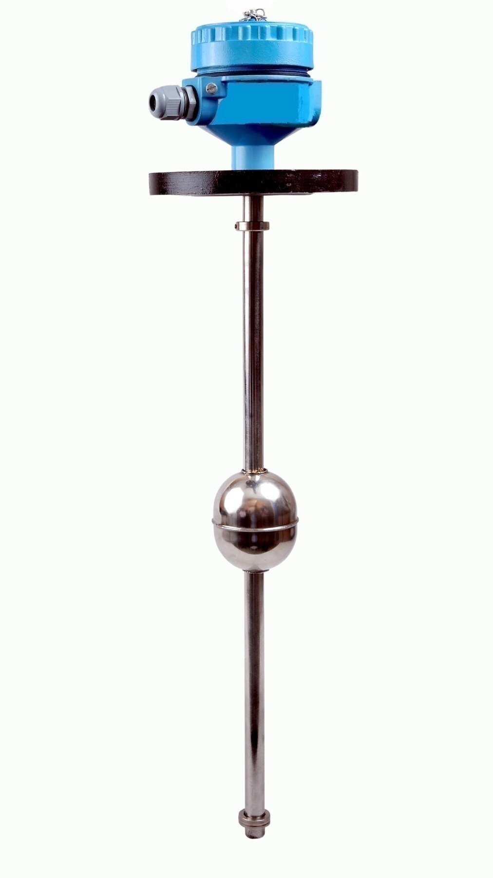
A float level transmitter follows the vertical position of a buoyant float and turns that movement into a continuous electrical signal for a control system or display. By the end, you will know how it differs from a level switch and mechanical indicator, how to specify and wire one, and when another level measuring method is the better choice.
Key takeaways
- Choose a transmitter for continuous level measurement, not simple high- or low-level alarms.
- Check float buoyancy, guide clearance, liquid density, temperature and pressure before ordering.
- Specify output, measuring range, process connection, materials and hazardous-area requirements.
- Scale the signal to tank level, then verify calibration at known liquid heights.
How a Float Level Transmitter Measures Liquid Level
Float level transmitter explained simply: it is a continuous level measuring instrument in which a buoyant float follows the liquid surface. The float measures vertical position, not pressure or liquid weight, so it needs enough buoyancy, clearance and freedom to move throughout the required range.
A position-sensing mechanism converts that movement into a usable signal. In a top-entry design, the float travels along a stem inside the tank and may couple magnetically to the sensor through the stem wall.
An external bypass chamber places the float beside the vessel; its connections must remain open so the chamber level matches the tank level.
The transmitter usually sends a 4–20 mA signal, with HART or another digital protocol available on some models. For example, 4 mA might represent the tank’s defined zero point and 20 mA the defined span. A float level switch is different: it changes a contact at a fixed point instead of reporting continuous level.
A mechanical float-and-board indicator shows level locally but does not provide a remote electrical signal.
A search for “level measuring instruments float level transmitter” should lead you to verify the complete measurement path, not just the electronics:
- Reference the measuring length to the tank bottom or another defined zero.
- Confirm free float travel without sticking.
- Check signal direction, scaling and loss-of-power alarm action.
- Compare the displayed value with an independent level reference.
A constrained float can produce a believable but incorrect reading. Density also matters: a float near its buoyancy limit can sink or shift its immersion as the liquid changes.
Transmitter, Float Switch or Mechanical Indicator?
Choose a float level transmitter for continuous monitoring; choose a float switch for a fixed alarm or control point; choose a mechanical indicator when someone only needs to read the tank locally.
| Option | Signal or display | Best fit |
|---|---|---|
| Float level transmitter | Continuous electrical output, commonly 4–20 mA with optional HART, for a PLC, DCS or remote display | Inventory, batching, pump control and level trending |
| Float level switch | Discrete contact at one or more preset levels | High-level alarm, low-level alarm or simple pump start/stop |
| Float-and-board mechanical indicator | Local pointer or board follows the float without electrical output | Tanks checked beside the vessel where remote monitoring is unnecessary |
A transmitter gives you level across the float’s travel, so the control system can respond before a fixed alarm point is reached. A switch is simpler for an independent point alarm because it needs less configuration and provides a direct contact.
A mechanical indicator is enough when an operator can safely see the tank and record readings locally. It becomes inadequate when the tank is distant, enclosed, hazardous to access or part of an automated process.
Check the mounting arrangement before choosing. A top-entry float needs a clear guide tube or stem, adequate float clearance and a defined zero reference, such as tank bottom or transmitter datum. An external chamber adds an accessible visual scale, but blocked or isolated vessel connections can make its reading wrong.
These distinctions separate useful level measuring instruments from devices that merely appear interchangeable.
Where It Works—and What Can Make It Misread
Reliability depends on more than tank height. A float level transmitter works when the float has enough buoyancy, clearance and travel to follow the liquid surface without touching the vessel, guide or internal fittings.
Confirm these process limits before selecting it:
- Minimum and maximum specific gravity: a float sized for water can sink in a denser-than-expected process or lose usable travel in a low-density liquid.
- Viscosity and solids: thick liquid, sludge, crystals or suspended particles can restrict movement or coat the float.
- Temperature, pressure and corrosion: these determine the float, stem, seals, guide tube and process-connection materials.
- Measuring length and reference point: define whether zero is the tank bottom, a lower connection or another datum.
- Connection size and orientation: a top-entry installation needs enough vertical clearance for the float and its full travel.
A guide tube or stem helps in turbulent tanks, but it must remain straight and free of deposits. Agitators, inlet jets, coils and internal ladders can push the float aside, producing a believable but wrong signal. Keep the float away from tank walls and obstructions across the entire range.
Density changes deserve attention. A float near its buoyancy limit can shift its immersion as specific gravity changes, adding level error. That matters for float level transmitter uses such as continuous feedback to a PLC, DCS or display, where a small error can alter batching or pump control.
A 4–20 mA output alone does not qualify the device for independent overfill protection or a safety instrumented function.
The Specification Checklist Before You Order
Before ordering, write down the liquid, vessel geometry, signal requirements and hazardous-area classification—not just the tank height. A float level transmitter can give a plausible but wrong reading if density, float travel or the zero reference is wrong.
- Process: minimum and maximum specific gravity, viscosity, temperature, pressure, corrosiveness, solids, agitation and coating tendency. Confirm whether the vessel is pressurised.
- Mechanical: required measuring length, tank-bottom or nozzle datum, top-entry or side-entry mounting, process-connection size and orientation, float diameter, guide tube or stem, and clearance from walls, coils and inlet flow.
- Electrical: supply voltage, 4–20 mA or 0–10 V output, HART requirement, maximum loop load, cable-entry thread, enclosure rating and the required action when power or signal is lost.
- Hazardous area: zone or division, gas or dust group, temperature class, ambient temperature and whether the complete assembly—not only the sensor—has the required ATEX, IECEx or local certification.
| Category | Confirm on the specification sheet | What goes wrong if omitted |
|---|---|---|
| Process | Minimum specific gravity and density variation | The float can sink or shift level as buoyancy changes |
| Mechanical | Travel, datum, connection and clearances | The float can stop early, rub or report a displaced zero |
| Electrical | Supply, output, load and cable entry | The loop can saturate or fail to communicate |
| Hazardous area | Zone, gas group and temperature class | Installation approval can be rejected |
Filpro Sensors Pvt Ltd can help match the application details to a model, but you should provide the vessel drawing and process data rather than select by nominal range alone.
Related products
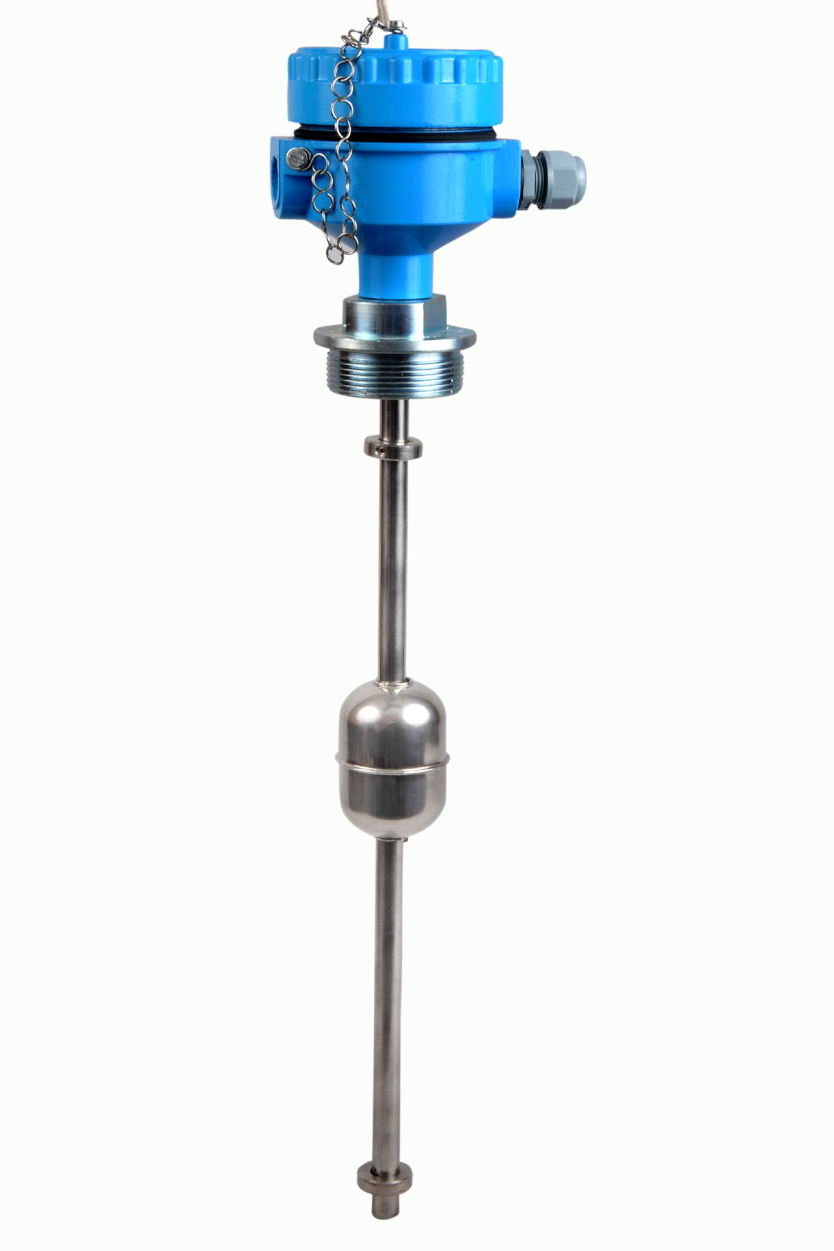 | Level Transmitter Float Level Transmitters Are Ideal For Continuous Level Monitoring In Water, Diesel, Chemical And Oils For Accurate Level Measurement. View product → |
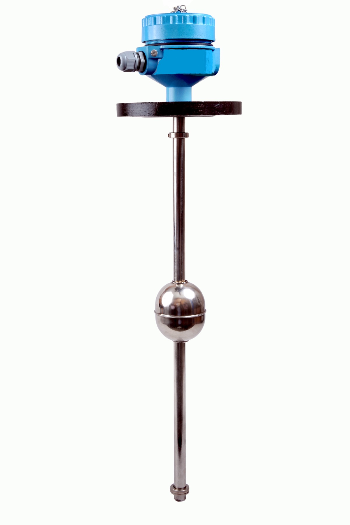 | Level Sensor Atex approved Float Level Transmitter : Over All Length: 300mm to 5000mm Input: 16V DC to 30V DC Output: 4-20mA / 0-10V DC Resolution: 5mm / 10mm... View product → |
Wiring, Scaling and Calibration After Installation
The float level transmitter explained earlier needs a complete loop check, not only an output test. Wire the transmitter, cable, input card and display as one measurement chain.
For a two-wire unit, connect the DC supply, transmitter and PLC or indicator input in series, observing terminal polarity and any barrier or isolator instructions. Confirm the supply voltage under load before calibration.
Record the actual lower and upper reference points. The lower point might be the tank bottom; the upper point is the specified float travel limit, not necessarily the vessel roof. The required verification depends on the float level transmitter uses and the assigned safety action.
1. Move the float through its range by hand or with a controlled level change. Confirm free travel, no sticking and agreement between float position and liquid surface.
2. Set the input scale so 4 mA equals the lower reference and 20 mA equals the upper reference. Reversed scaling creates a convincing but wrong reading.
3. Check the display at a known intermediate level. If it shows volume, enter the tank’s actual geometry instead of treating a non-linear tank as a straight scale.
4. Trigger low and high alarms, then interrupt power or the signal. Confirm the configured fault state and recovery action.
5. Compare the final display with an independent sight glass or dip measurement. Investigate any offset before accepting the loop.
A float that stops short of its reference or a plugged bypass connection can leave the electrical loop calibrated while the displayed level is wrong. Record the commissioning results.
Frequently asked questions
How does a float level transmitter measure liquid level?
A buoyant float follows the liquid surface, and the transmitter converts its vertical position into a continuous level signal. It measures position rather than pressure or liquid weight.
Should you choose a float level transmitter, float switch or mechanical indicator?
Choose a transmitter for continuous measurement, a float switch for one or more on/off alarms or controls, and a mechanical indicator when you need a local visual reading without an electrical signal.
What can make a float level transmitter misread?
Insufficient buoyancy, liquid-density changes, restricted float movement, turbulence, buildup, a tilted installation or an unsuitable measuring range can produce inaccurate readings.
What should you specify before ordering a float level transmitter?
Provide the measuring range, tank dimensions, liquid density and temperature, pressure, viscosity, float and wetted-part materials, process connection, output signal, power supply, enclosure and hazardous-area requirements.
How do you calibrate a float level transmitter after installation?
Confirm free float movement, set the zero and span or configured low and high points, scale the output to tank level, and compare readings with known liquid heights.