A level indicator can show the wrong reading even when its scale, float and connections appear intact: an incorrect datum, blocked process connection, poor alignment or unsuitable wetted material can invalidate the installation. By the end, you will have a practical sequence for selecting the arrangement, preparing the tank, mounting and wiring the instrument, calibrating it, commissioning it and recording the results.
Key takeaways
- Match the indicator’s zero and span to the tank’s actual measurement points.
- Isolate, drain, depressurise and purge the tank before installation.
- Keep floats, chambers and transmitters clear of turbulence and obstructions.
- Record wiring checks, calibration results and final level readings before handover.
Confirm the instrument, process and measurement range before touching the tank
Verify the selected indicator against the tank’s measurement points, liquid, process conditions and required range before touching the tank. A level indicator installation guide should identify the reference datum: its marked zero and span must match the actual lower and upper sensing points, not automatically the vessel bottom and roof.
1. Measure the tank height, nozzle elevations and usable level range. Subtract blind zones, displacer length, float travel and any unmeasured space above or below the connections; these can make the displayed range shorter than the vessel’s capacity.
2. Confirm the scale basis. Hydrostatic level does not change when liquid density changes, but density affects a float or displacer and can invalidate a mass or volume scale calibrated for another liquid or tank geometry.
3. Match the wetted parts to the actual liquid. Check the float’s specific gravity, corrosion compatibility, and pressure and temperature ratings. High viscosity or solids can stop a correctly sized float from moving.
4. Check every bridled chamber’s isolation valve, gasket, bolt and connection rating against the vessel’s design pressure and temperature. The valves enable maintenance isolation and a controlled leak test before commissioning.
5. Inspect the installation path. A direct-mounted indicator needs hydraulically open lower and upper connections to the liquid and vapour spaces; a plugged or partly closed line can hold a false reading. Align chamber connections to prevent trapped gas at the top and sediment at the bottom, and ensure the chamber can vent and drain.
Only proceed when the instrument range, datum and process conditions agree with the tank drawing and site measurements.
Make the tank safe and prepare the installation site
Before mounting, make the tank safe, verify the connection geometry, and clear a stable working area. Use a level indicator installation guide alongside the approved tank drawing, nozzle schedule, P&ID, and instrument datasheet.
1. Isolate the tank with lockout/tagout, close and lock process valves, depressurise, drain, purge, and prove zero pressure. Test for toxic, flammable, or oxygen-deficient atmospheres before entry or hot work.
2. Mark the instrument’s reference datum on the drawing and tank. The zero and span points must match the actual measurement points; nozzle elevation, blind zones, displacer length, and float travel can make the usable indicated range shorter than the vessel height.
3. Check tank height, nozzle centreline elevations, flange size and rating, bolt pattern, chamber length, float clearance, scale position, and operator access. Confirm that supports will not distort the tank shell or indicator.
4. For bridled instruments, install rated isolation valves, gaskets, bolts, and connected chamber components. Match every part to the vessel design pressure and temperature, then plan a controlled leak test before commissioning.
5. For direct-mounted indicators, confirm that the upper and lower connections are open to the vapour and liquid spaces. A closed, plugged, or partly blocked connection can produce a steady false reading.
6. Confirm magnetic-float orientation and rail compatibility. On hot service, plan tracing or insulation without covering the scale, blocking valves, restricting access, or exceeding the indicator temperature limit.
Do not treat a volume scale as universal: liquid density can alter float or displacer behaviour even though hydrostatic level remains unchanged.
Mount each level indicator arrangement without creating a false reading
Install each indicator against the tank’s actual measurement datum, then support it without transferring pipe strain into the vessel nozzle or instrument body. The marked zero and span must match the intended liquid levels; nozzle elevation, blind zones, float travel and displacer length can make the visible range shorter than the tank’s usable volume.
A level indicator installation guide should also show a safe viewing position.
- Float-and-board: Mount the board vertical, align the pulley with the float centreline, and route the rope without rubbing. Give the float full travel and prevent it touching the tank wall, coil or roof.
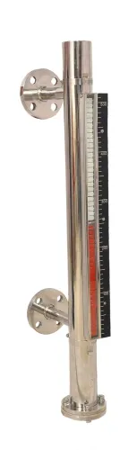
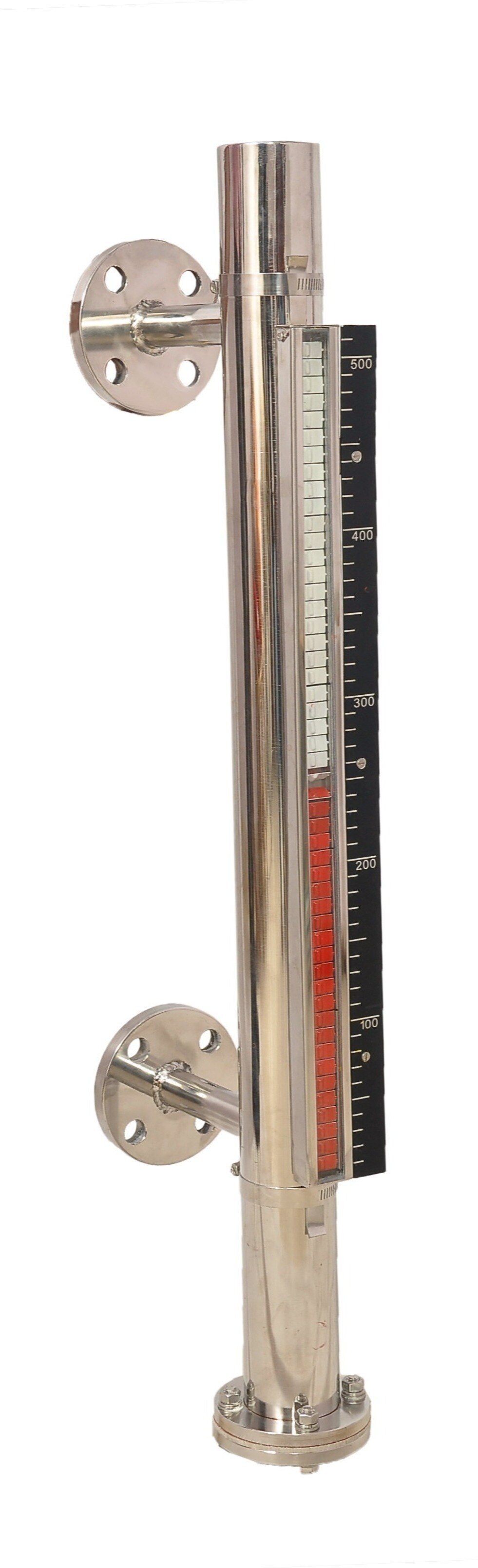
- Magnetic: Install the chamber in the manufacturer’s marked orientation, with the float magnet matched to the indicator rail. An upside-down chamber can leave the follower outside the scale or resting at the wrong end.
- Tubular glass: Keep the gauge vertical, fit the specified isolation and drain valves, and leave the scale visible. Do not place an operator below pressurised glass.
- Oil: Mount the gauge level and upright, keep its connection passages free of trapped gas or sediment, and confirm the fluid inside matches the scale’s intended service.
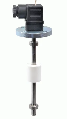
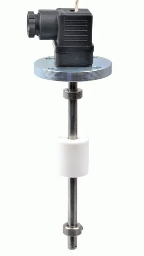
- Switch: Align the float or displacer with unobstructed travel, then support the switch separately from vibrating or unsupported piping. Set actuation points against the marked datum.
- Transmitter: Fix the probe or displacer concentrically, protect cable entries, and calibrate zero and span after connection.
For hot service, insulate or trace only within the instrument’s temperature limit; never cover the scale, valves or moving parts. A chamber must vent at the top and drain at the bottom.
Wire, calibrate and commission the indicator
Connect the instrument exactly as its terminal diagram shows. Match the supply voltage, polarity, signal wires and protective earth; terminate the cable shield at the specified end, and keep low-level signal wiring separate from motor or power cables. For a 4–20 mA instrument, verify loop polarity and load before energising it.
A level indicator installation guide must define the reference datum before calibration. Set zero and span against the tank’s actual lower and upper measurement points, including nozzle elevations, blind zones, displacer length or float travel—not automatically against the vessel bottom and top.
- Keep bridled isolation valves accessible, verify their pressure and temperature ratings, and perform a controlled leak test before opening the instrument to the process. Check that a direct-mounted indicator has open, correctly valved lower and upper connections; a blocked connection can produce a steady false reading.
- At a known low or zero level, record the actual level, local indication, valve positions and any offset. Adjust zero, then check span at a second known level; repeat the adjustment if the error changes across the range.
- Compare the local reading with the PLC, DCS or control-room display at both reference levels. Investigate mismatches in scaling, signal polarity, loop configuration or datum location instead of accepting movement of the float as proof.
- Record the tag, model, float identification, design conditions, connection rating, calibration readings and as-left valve positions. Ensure supports carry piping loads, not the chamber or vessel nozzle.
Record acceptance results and plan maintenance
Record acceptance results in the level indicator installation guide, not only the installation date. Include tag number, model, serial number, reference datum, zero and span elevations, vessel design pressure and temperature, test method, readings, observer, date, and deviations accepted.
1. Perform the leak check with the process isolation valves closed, then inspect the chamber, flanges, gaskets, bolts, drain, vent and sight element. Record the test medium, pressure, hold time and result; use the approved pressure-test value and never exceed the lowest-rated component.
2. Fill and equalize a bridled chamber gradually. Opening either valve abruptly can create a surge, strike the float, or release hot liquid through damaged glass. Record stable indication against an independent tank reading.
3. Log each fault as symptom, probable cause, check, corrective action and verifier. Check trapped gas, blocked drains, misaligned connections, stuck floats, damaged magnetic flags, loose wiring and incorrect datum before removing parts. Isolate and depressurize before opening anything.
4. Set inspection intervals for visibility, leakage, indication error, valve operation and fastener condition, with shorter intervals for corrosive, hot, vibrating or dirty service. Record every inspection and the condition that triggers unscheduled work.
5. List tagged spares by instrument: glass, mica shield, gaskets, packing, retainer hardware, float, magnetic indicator elements, switches, transmitter parts, bolts and isolation-valve seals. Include material, dimensions, pressure-temperature rating, supplier, storage location and quantity. Filpro Sensors Pvt Ltd can help verify compatibility when the model, service and spare specification are recorded.
Related products
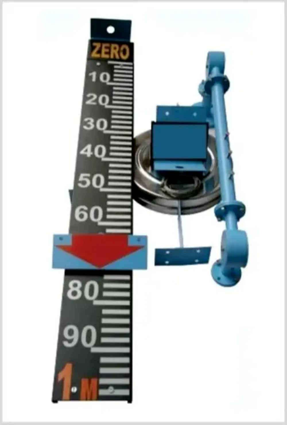 | Level Indicator The Float & Board Level Indicators consists of a float connected to a pointerthrough a rope via a set of pulleys. View product → |
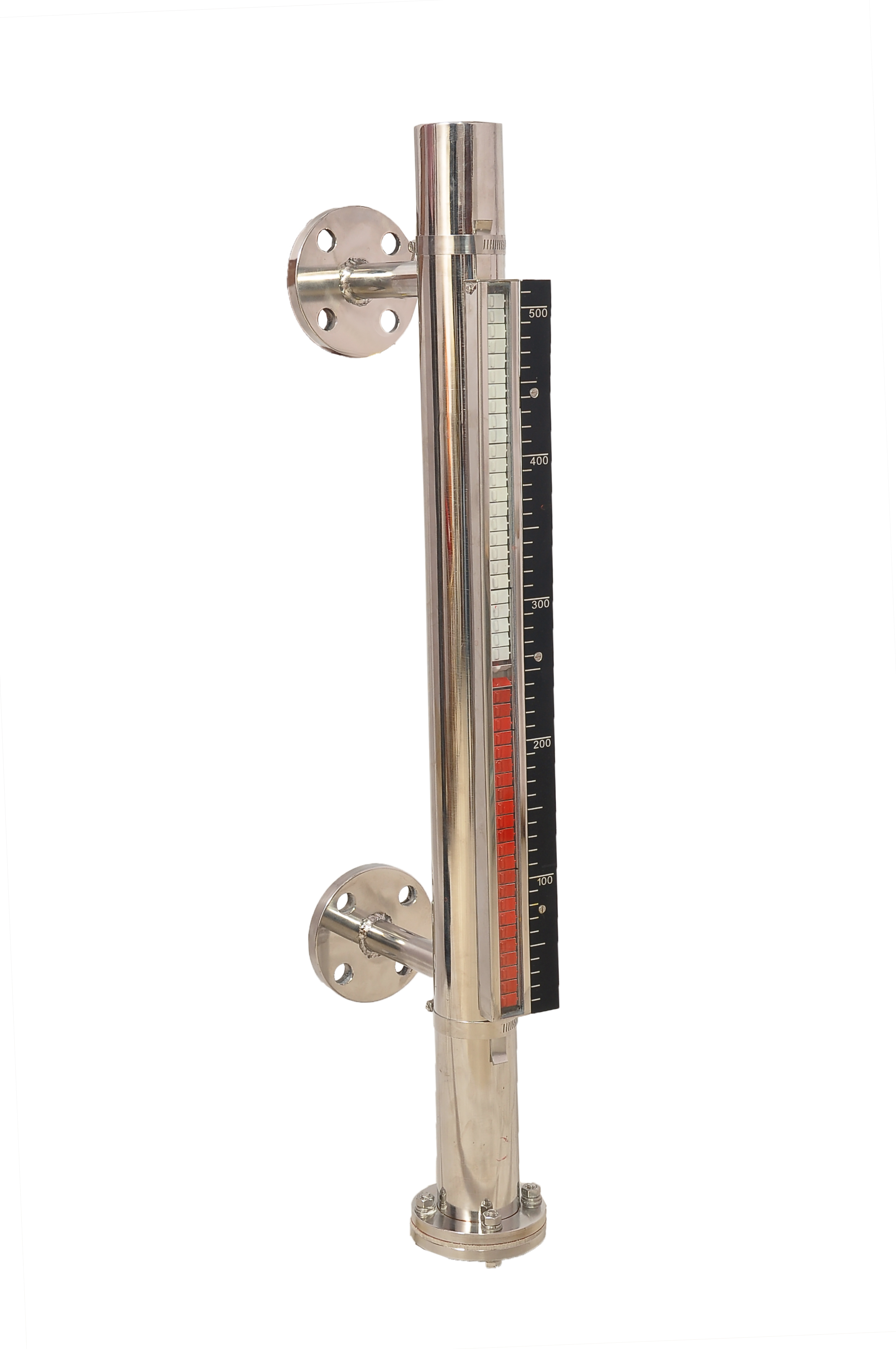 | Level Gauge FILPRO offers Magnetic Level Indicator provides clear, high clarity indication of liquid level. View product → |
Frequently asked questions
What must you confirm before installing a level indicator?
Confirm the instrument type, tank measurement points, liquid compatibility, process conditions and required measurement range. Match the marked zero and span to the actual lower and upper sensing points.
How do you make a tank safe for level indicator installation?
Follow the site permit procedure, isolate connected equipment, drain and depressurise the tank, and purge it when the liquid or vapour presents a hazard. Verify zero pressure and atmospheric conditions before opening connections.
How do you prevent a level indicator from showing a false reading?
Mount the instrument at the correct reference points, keep floats and probes clear of internal obstructions, avoid turbulent inlets, and check that chambers and impulse connections are not blocked or air-locked.
What should you check when commissioning a level indicator?
Check wiring against the terminal diagram, verify power and signal polarity, compare indicated level with a known level or reference measurement, and document zero, span, alarm and output results.
Related products
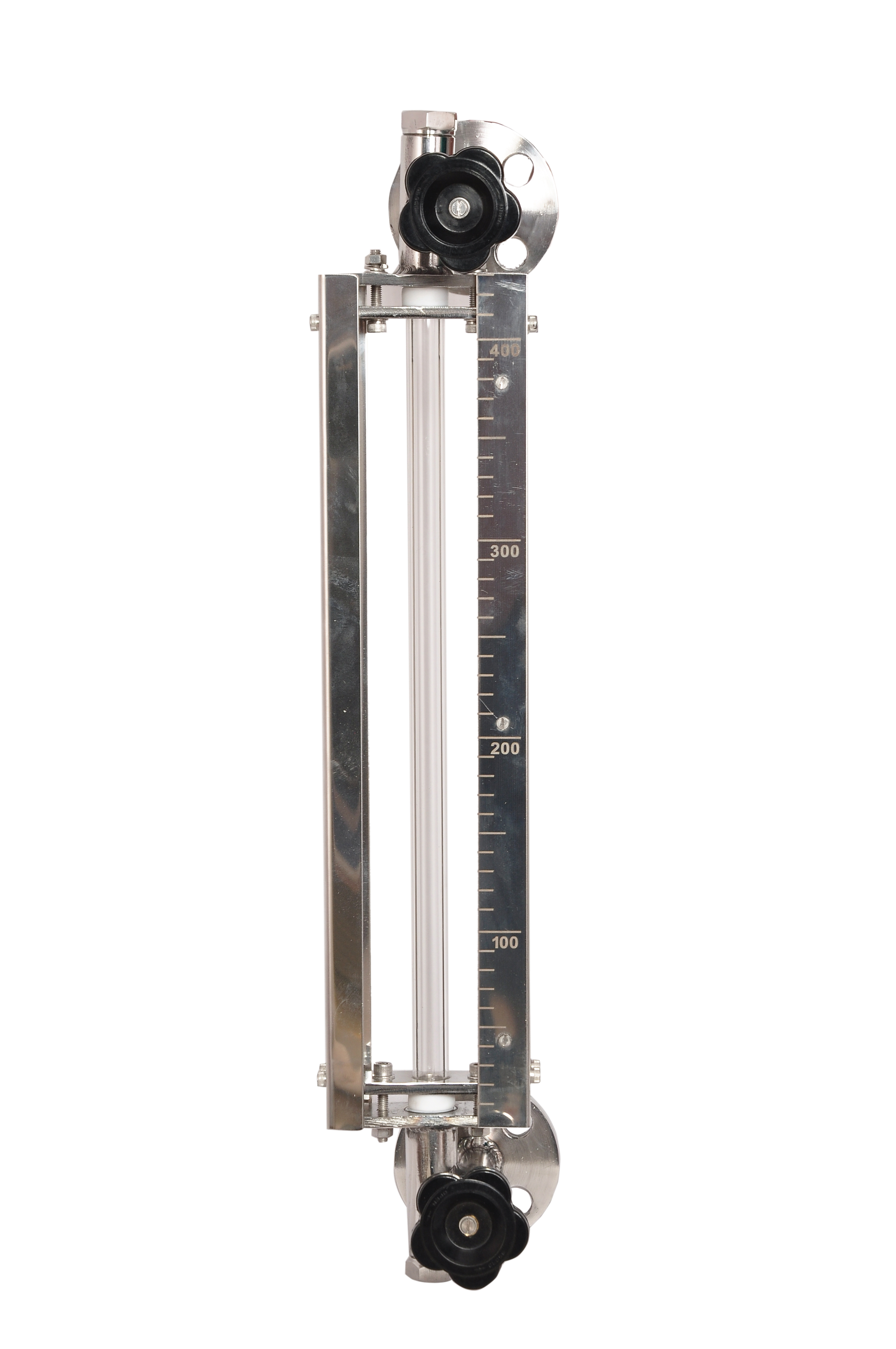 | Level Gauge Tubular Glass Level Indicator is used for visual level indication of liquid in storage and process tanks. View product → |
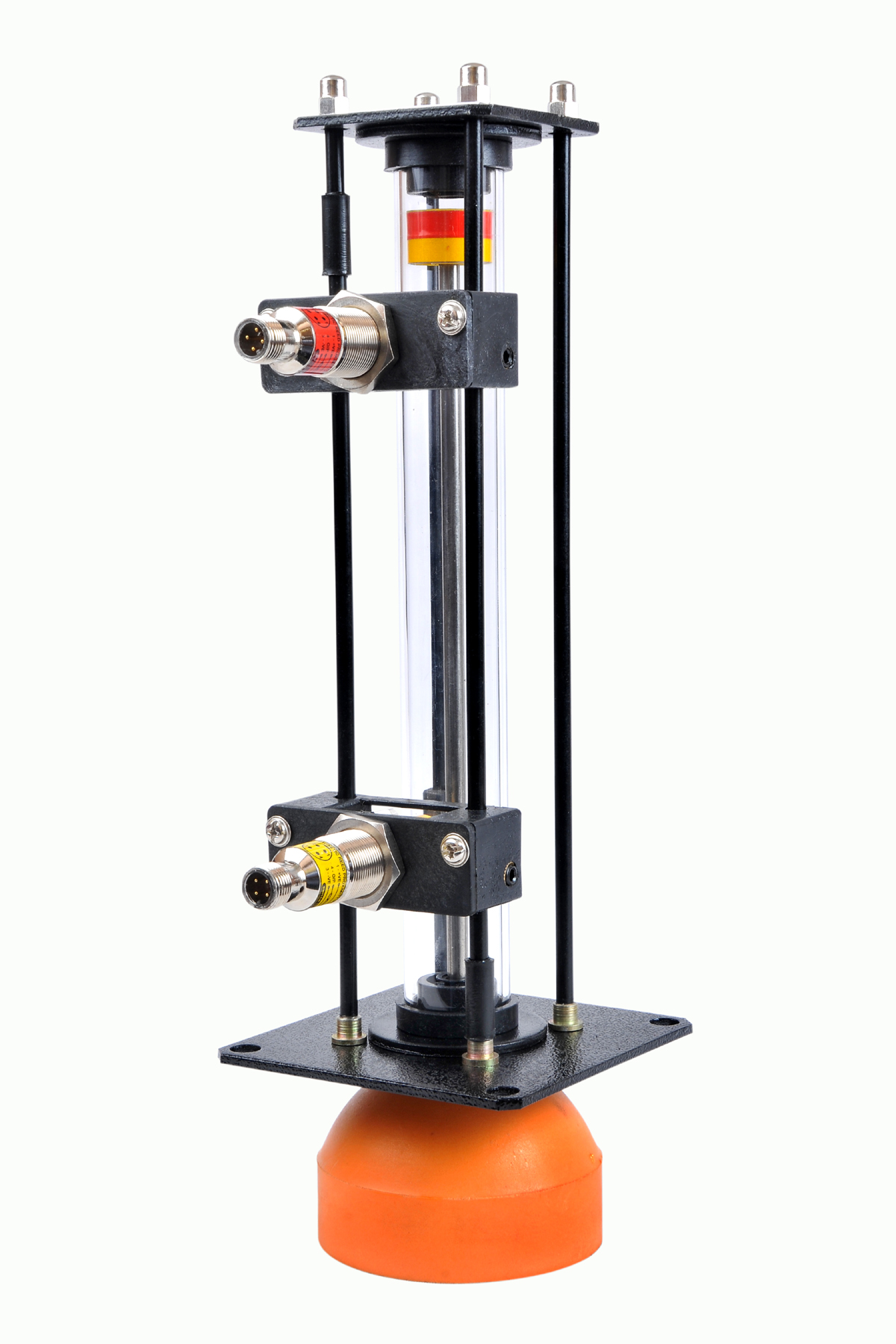 | Level Gauge Oil Level Indicator is designed to indicate the coolant and hydraulic oil level inside the tank with a visual indicator above the tank. View product → |
 | Level Switch Filpro offers most reliable, cost effective Side Mounted Level Switch for point level sensing. View product → |
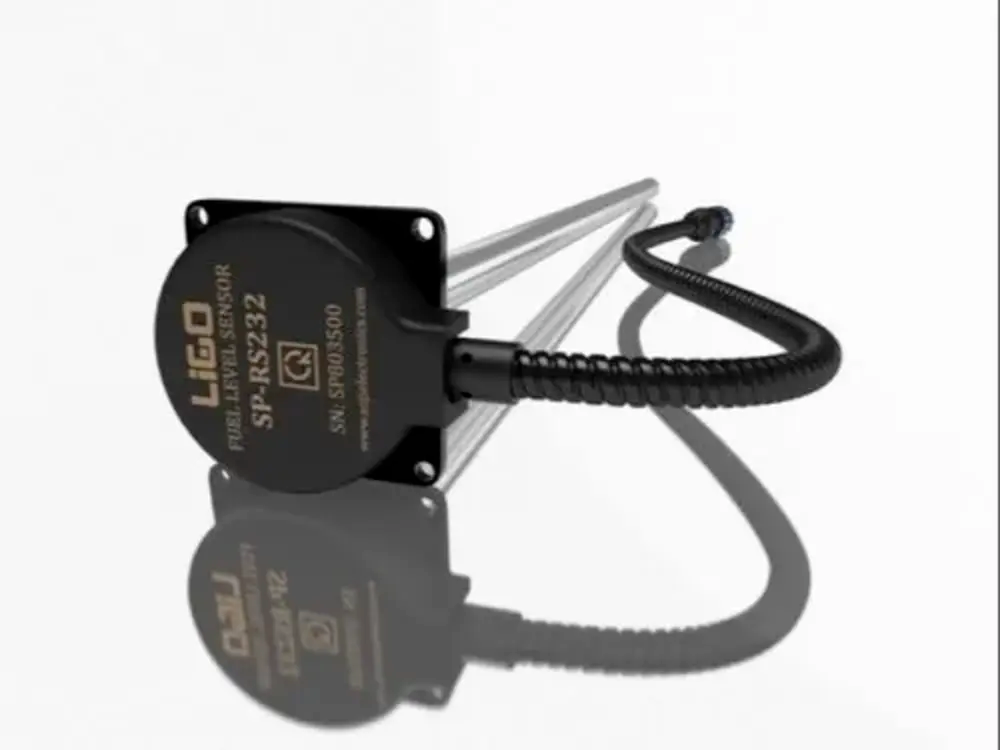 | Level Sensor Ligo fuel sensor for monitoring Diesel and Petrol level in vehicle fuel tanks and DG sets. View product → |