A safe panel does more than display tank level or send a start command to a pump. You need to match the sensing method to the liquid, separate control and power functions, protect the motor, define what happens during faults, and prove each trip during commissioning.
Key takeaways
- Separate sensing, control and motor-switching circuits.
- Document normal, alarm, trip and restart conditions before wiring.
- Select instruments for the liquid, tank and required failure response.
- Test every alarm, trip and automatic restart before handover.
Define the panel’s job before choosing its parts
A liquid level control panel receives tank signals, decides when equipment must start or stop, and sends protected commands to pumps, valves, alarms, or telemetry. Define that job before selecting parts: indication, automatic control, overfill shutdown, dry-run protection, or all four require different arrangements.
The core liquid level control panel components are:
- Enclosure, incoming isolator or circuit breaker, fuse or MCB, and surge protection where field wiring is exposed
- Power supply or control transformer, PLC, RTU, or relay logic, with analogue and discrete input/output
- Sensor terminals and interfaces for 4–20 mA, pulse, switch, or intrinsically safe signals
- Independent high-high level switch, alarm beacon or horn, local/remote selector, emergency stop, and test or isolation points
- Contactor or motor starter, correctly sized overload relay or motor-protection circuit breaker, and phase-loss or phase-sequence protection
- Numbered terminal blocks, ferrules, labelled field wiring, earthing hardware, and separate control and power wiring routes
| Device | Makes the level decision or action | Purpose |
|---|---|---|
| Level sensor | Measures continuously | Sends level data |
| Level switch | Detects a set point | Starts an independent trip or alarm |
| Controller | Interprets inputs | Commands the output |
| Contactor or starter | Switches motor power | Runs the pump; overload protection guards the motor |
Specify the available fault current and component combination rules so the panel’s marked SCCR is adequate; normal motor current alone is not enough. State liquid conductivity, foam, solids, vapour, temperature, pressure, agitation, and tank geometry before choosing float, conductive, ultrasonic, radar, hydrostatic, or guided-wave radar measurement.
Classified areas also require approved protection methods, barriers or isolators, segregation, and wiring practices.
Build separate sensing, control and motor-switching circuits
The signal path should be: tank sensor, field terminals, isolated controller input, control logic, output relay or drive command, motor starter, and pump. Keep sensing, control, and motor-switching circuits separate. The sensor reports level; the controller makes the decision; the contactor, starter, or VFD switches motor power.
Specify the liquid level control panel requirements as a wiring and protection schedule:
- Use numbered terminals and ferrules, with a test or isolation point for every field device.
- Route 4–20 mA, pulse, and switch wiring separately from motor and VFD output cables; shield analogue cables and ground shields according to the instrument manufacturer’s instructions.
- Provide a lockable supply disconnect, short-circuit and overcurrent protection, documented protective earthing, and control-circuit protection that prevents automatic motor restart after power returns.
- Mark the panel’s short-circuit current rating (SCCR) from the available fault current and the coordinated ratings of fuses, circuit breakers, contactors, overloads, and drives. Motor running current alone does not establish SCCR.
- Add surge protection when long outdoor cables or lightning exposure can reach the panel.
IEC 60204-1 provides the framework for machine electrical equipment, including disconnecting, shock protection, overcurrent protection, emergency stop, and control-circuit protection. For a VFD pump, define whether a level trip removes the run command, opens a safety circuit, or uses the drive’s safety-rated input; a PLC output alone is not a safety-rated stop.
Use an independent high-high level switch for overfill shutdown, rather than relying on the same transmitter that provides normal indication. A failed or isolated transmitter must not defeat both functions.
Write the control philosophy for normal operation and faults
Normal operation starts with a defined level band. The controller starts, stops, or modulates the final element within that band, while start and stop delays prevent rapid cycling. In automatic mode, a pump must run only when its permissives are healthy; a valve must move only within its configured travel and process limits.
Set the high-high action to protect against overflow: stop the filling pump or close the inlet final element, then latch the trip until an authorised reset. Set the low-low action to protect against dry running or loss of suction: stop the transfer pump or close the outlet final element.
Record the chosen action in the cause-and-effect matrix rather than assuming every tank uses the same response.
High and low alarms warn the operator before the trip point and require a defined response. Do not label every diagnostic an alarm; a failed transmitter, drive fault, or communication loss needs its own response and priority.
Manual control must not defeat high-high, low-low, emergency-stop, overload, or dry-run protection. A manual start requires the same permissives as automatic operation, and a cleared fault must not restart the motor without a deliberate reset and start command.
Define fault behaviour for a broken signal, lost power, failed transmitter, controller failure, and VFD trip. Test whether each condition stops the final element, holds it in a safe position, or raises an alarm.
Commissioning must wet-test actual or simulated levels, verify every alarm and trip setpoint, prove final-element action, complete loop and fail-signal tests, check pump rotation, and test alternation and restart logic. Keep the signed cause-and-effect matrix with the records.
Match the level instrument and panel architecture to the process
Choose the instrument from the process, not from the tank’s stated level range. Conductivity, dielectric constant, foam, viscosity, solids, vapour, temperature, pressure, agitation, coating and tank geometry can change the correct measurement principle.
| Option | Process fit | Design check |
|---|---|---|
| Conductive probe | Conductive liquids and point-level control | Provide a reference electrode; it will not sense insulating liquid. |
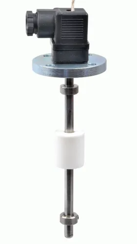
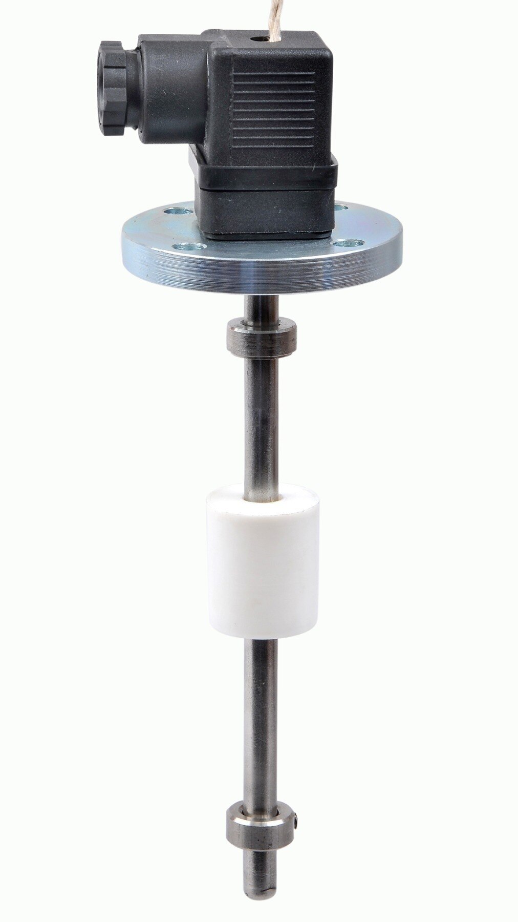
| Float switch | Clean liquids with stable movement | Check turbulence, density, hinge clearance and coating. |
| Capacitance | Interface or level detection through a vessel wall | Confirm dielectric constant and compensate for buildup. |
| Ultrasonic or radar | Non-contact measurement | Check foam, vapour, obstructions, dead zones and beam geometry. |
| Hydrostatic or guided-wave radar | Pressurised, narrow or obstructed vessels | Confirm pressure, temperature, probe length and material compatibility. |
The liquid level control panel components must match the motor method. A contactor and overload relay suit direct-on-line starting; a soft starter or VFD needs compatible control wiring, motor thermal protection, fault handling and minimum-speed or minimum-flow limits. A PLC output alone is not a safety-rated stop.
Specify the disconnect, branch protection, earthing and panel short-circuit current rating from available fault current, not motor running current.
For classified areas, identify the zone, gas or dust group, temperature class, protection method and wiring rules before selecting ordinary I/O. Intrinsically safe circuits need certified barriers or isolators, entity-parameter checks and segregation.
When reviewing a hydrostatic transmitter from Filpro Sensors Pvt Ltd, ask for diaphragm compatibility with the liquid and the specified pressure and temperature.
Related products
 | Level Switch Filpro offers most reliable, cost effective Side Mounted Level Switch for point level sensing. View product → |
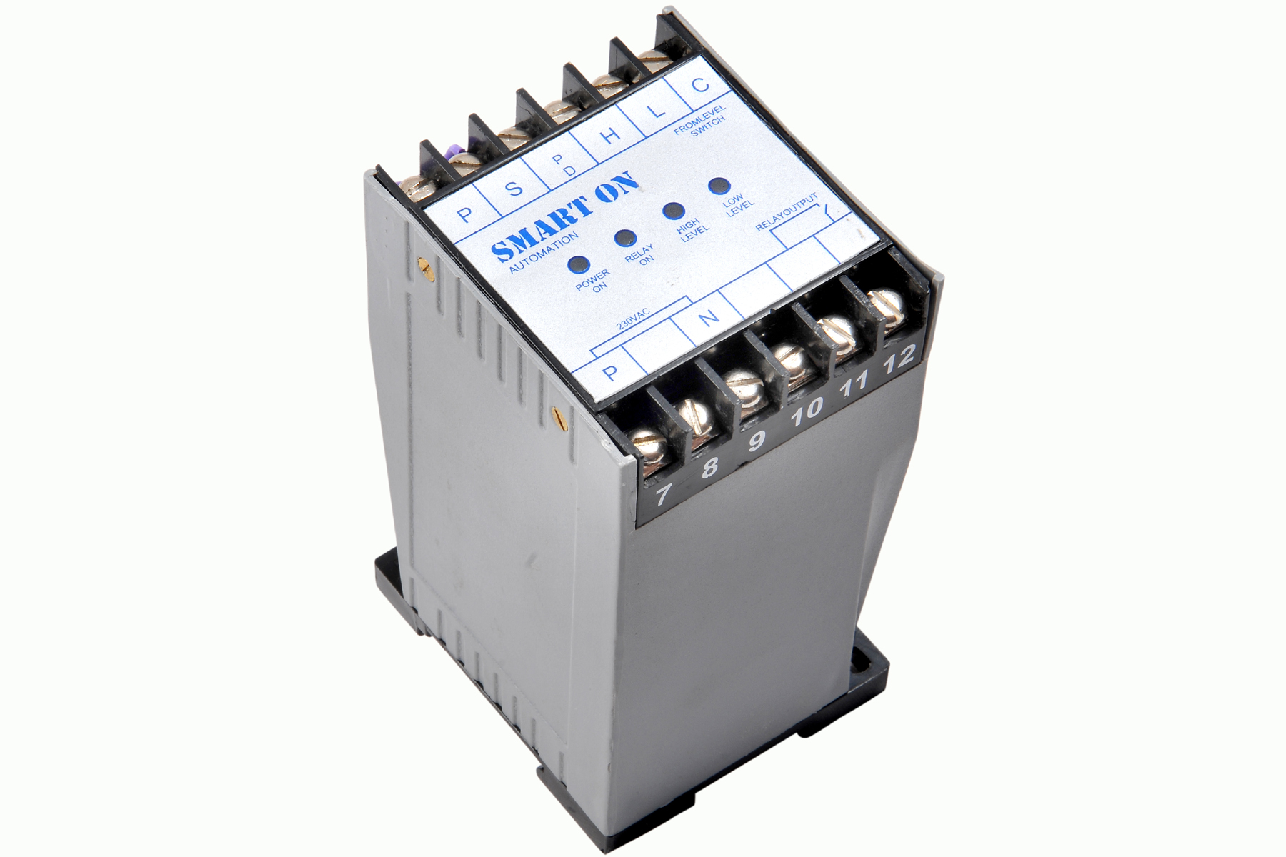 | Controller Filpro Sensors Pvt Ltd manufactures industrial Level Controller (Smart On) to automatically start & stop the pump. View product → |
Prove every trip, alarm and restart behaviour before handover
A finished panel passes commissioning only when it proves the complete chain from process condition to final action. A displayed level is not evidence that a pump will stop, a valve will close, or an alarm will reach the operator at the specified limit. Record each result against the liquid level control panel requirements.
1. Perform a loop check from every transmitter and switch to its terminal, input channel, displayed value and engineering unit. Confirm the 4–20 mA range, polarity, scaling and alarm thresholds.
2. Wet-test actual or simulated levels at every start, stop, high, high-high, low and low-low setpoint. Verify the intended final element: pump contactor, drive command, shutdown relay or valve.
3. Inject broken-wire, out-of-range, invalid-value, lost instrument power, failed communications and lost air conditions. Confirm whether the output de-energizes to trip, holds, or permits a controlled restart.
4. Check pump rotation, overload trips, dry-run interlocks, lead-lag alternation, minimum run and off times, hysteresis, and alarm priorities. Cycle power and prove that automatic restart, manual reset and emergency-stop behaviour match the approved philosophy.
5. Sign a cause-and-effect matrix with witnessed test results, failed-test corrections and retest dates.
Handover records should include the P&ID, loop drawings, I/O list, setpoints, calibration certificates, software revision, proof-test intervals, bypass permissions, short-circuit rating, and enclosure or hazardous-area certificates. Include the power-interruption test and protective-earthing verification under IEC 60204-1.
Frequently asked questions
What does a liquid level control panel need to control?
Define whether it provides indication, automatic start and stop control, overfill shutdown, dry-run protection, alarms or telemetry before selecting components.
Which circuits belong in a liquid level control panel?
Keep the sensing circuit, control circuit and motor-switching circuit distinct, with suitable protection and interfaces between them.
What should a control philosophy document include?
State normal operating sequences, high and low alarms, shutdown trips, sensor faults, power failures and restart behaviour.
How do you verify a liquid level control panel before handover?
Prove each level signal, alarm, trip, interlock and restart response under normal conditions and simulated fault conditions.
Related products
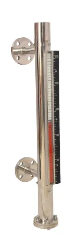
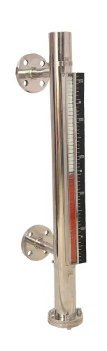
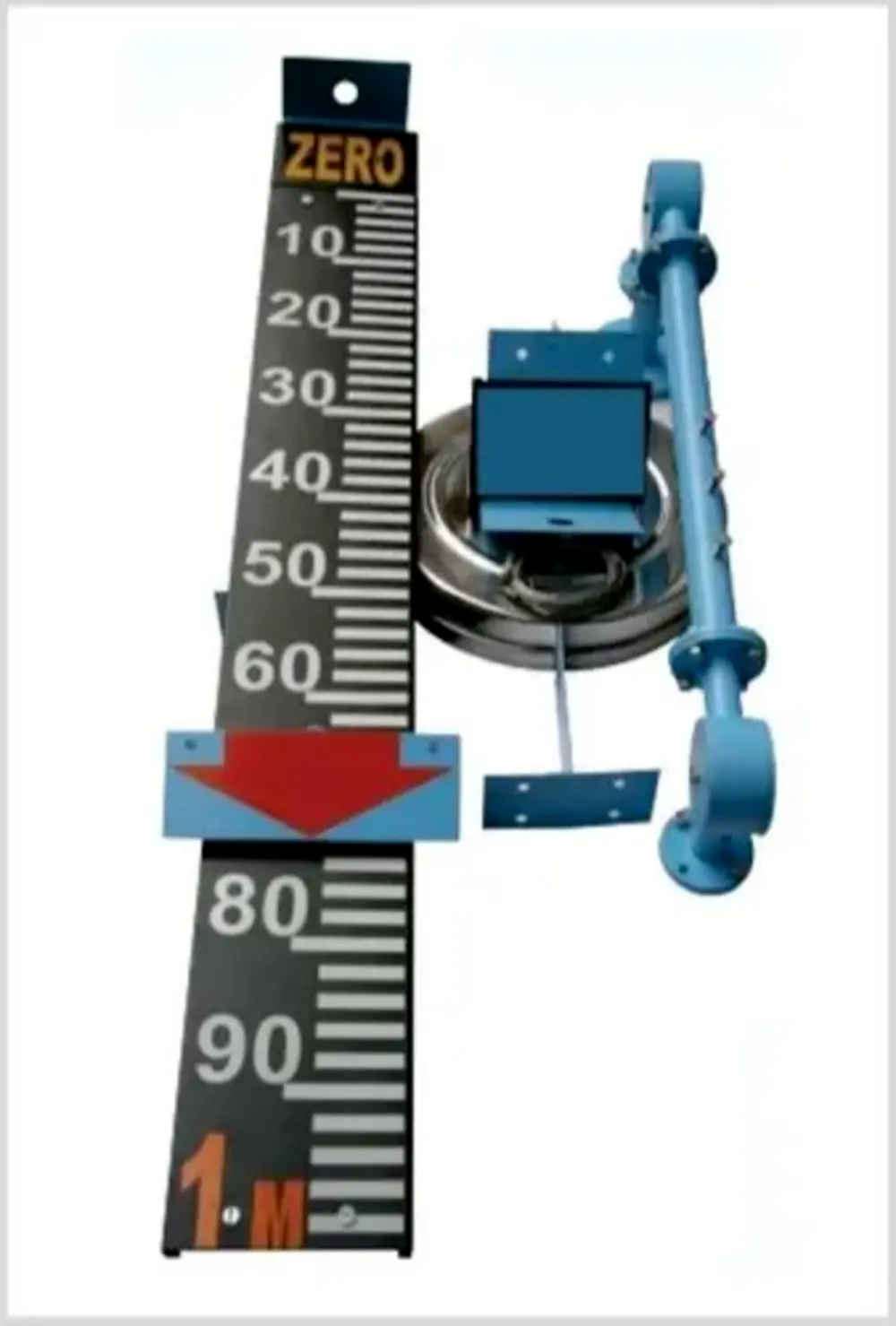 | Level Indicator The Float & Board Level Indicators consists of a float connected to a pointerthrough a rope via a set of pulleys. View product → |
 | Level Sensor Atex approved Float Level Transmitter : Over All Length: 300mm to 5000mm Input: 16V DC to 30V DC Output: 4-20mA / 0-10V DC Resolution: 5mm / 10mm... View product → |
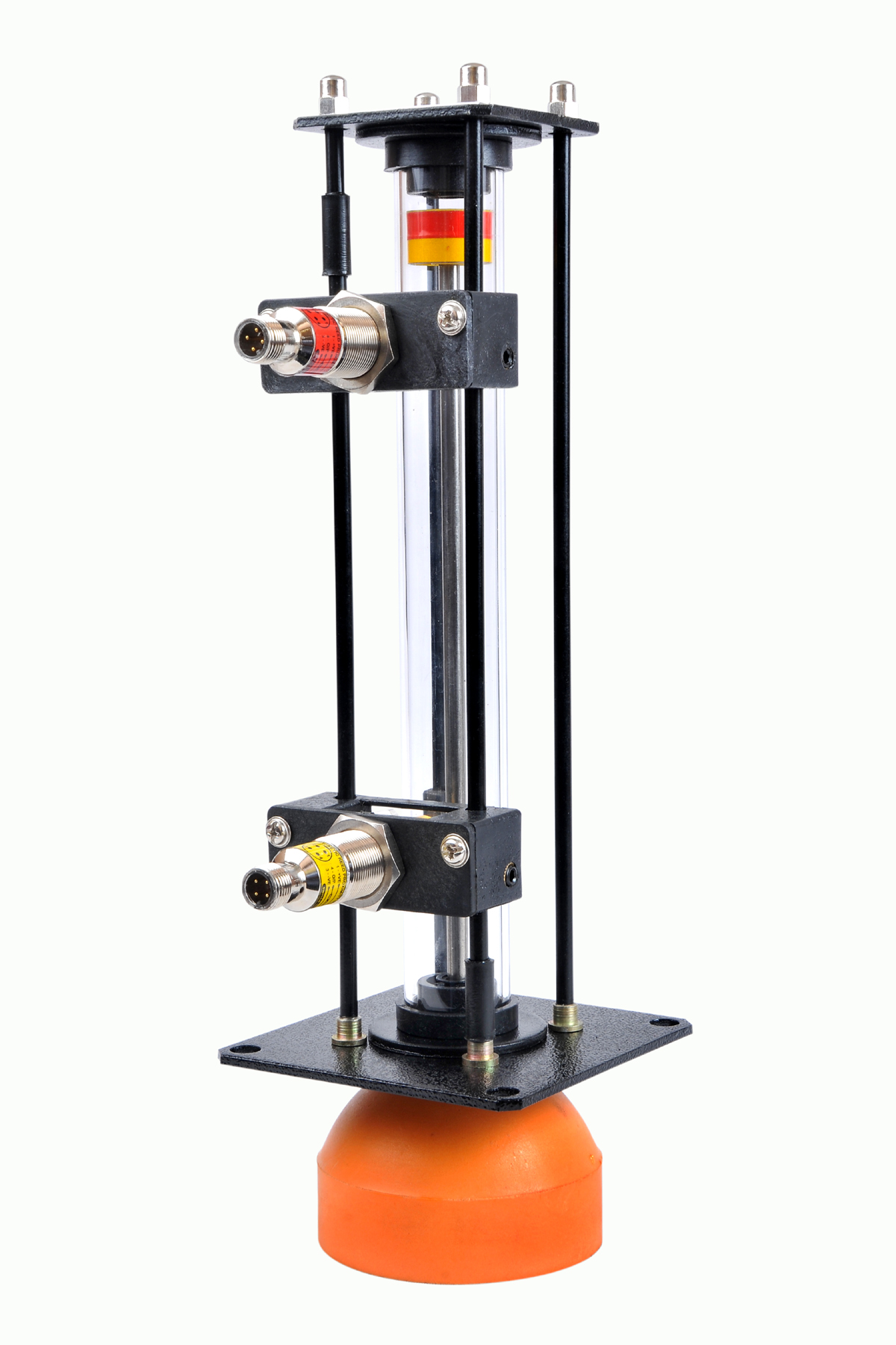 | Level Gauge Oil Level Indicator is designed to indicate the coolant and hydraulic oil level inside the tank with a visual indicator above the tank. View product → |
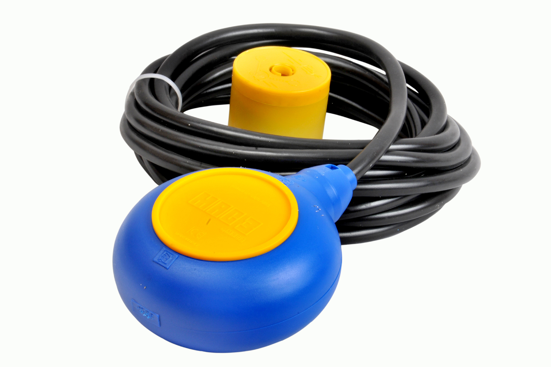 | Level Switch Cable Float Switch is mainly used for the automatic working of small pumps and cellar emptying pumps in liquids a little bit agitated. View product → |