Tank checks become unreliable when operators must climb to a gauge, copy a number without units, or trust a display that is incorrectly scaled. You will learn how the signal reaches a panel, how to interpret its status, when it improves routine checks, and when another level instrument is the better choice.
Key takeaways
- Check value, units, alarm state, signal quality, and live-or-held status.
- Mount the display where operators can read it without climbing the tank.
- Match the sensor output, display input, range, units, and alarm settings.
- Verify calibration, wiring, fail-safe alarms, and loss-of-signal behavior before service.
What a digital liquid level indicator panel actually adds to a tank
A digital liquid level indicator panel is a locally mounted display connected to a continuous level sensor or transmitter. It brings the measured value, units, alarm state, signal quality, diagnostic status, and live-or-held indication to a location where you can check the tank without climbing to the vessel.
It does not automatically improve the sensor’s underlying accuracy.
| Device | What it provides | Limitation |
|---|---|---|
| Digital liquid level indicator panel | Remote display of a continuous measured value | Accuracy remains limited by the sensor, installation, calibration, tank geometry, and process conditions |
| Transmitter’s built-in display | Value at the transmitter itself | Harder to read from a control room or safe ground-level location |
| Sight gauge | Direct visual indication through a connected tube or chamber | Fouling, blocked connections, and poor visibility can hide the true level |
| Magnetic or tubular glass gauge | Local mechanical or visual level indication | It does not provide the transmitter’s digital diagnostics |
| Point-level switch | A condition such as high, low, or full | It does not report the continuously measured level |
The signal path begins with a radar, ultrasonic, hydrostatic, float, or other level sensor. The sensor sends a 4–20 mA signal, HART data, or a Modbus protocol; the panel receives it, applies range and tank scaling, and displays millimetres, metres, litres, percentage, cubic metres, or mass.
Volume is correct only when scaling uses the tank’s actual strapping table or calibration points. A simple linear percentage gives the wrong volume in many horizontal cylindrical or irregular tanks. A panel repeats the transmitter’s value, so independent confirmation requires a second transmitter, sight gauge, dip measurement, or mass-balance check.
How to read the panel during a tank check
Read the displayed level and engineering unit first: litres, millimetres, percentage, or cubic metres. A digital tank level indicator panel must show that number beside measurement status, signal quality or diagnostic state, alarm state, and a timestamp; without them, a large value can be stale or incorrectly scaled.
- Compare the reading with the configured tank capacity and usable operating range, not just the vessel’s nameplate volume. Record whether the value is live, damped by filtering, or held as the last valid reading.
- Check the alarm state and its settings. High and low alarms mark operating limits; high-high and low-low alarms mark protective or urgent limits. Confirm the alarm deadband, which prevents chattering around a limit, and the alarm delay, which prevents a brief excursion from triggering it.
- Treat sensor fault, lost input current, out-of-range signal, communication failure, and power-failure indications as invalidating the reading until resolved. A held last-valid value must be labelled clearly, never displayed as current.
- Do not accept a stable number as proof of a valid measurement. Ultrasonic sensors can be misled by foam, vapour, condensation, or turbulence; radar can select false echoes or be affected by buildup; hydrostatic readings change when liquid density changes.
- Remember that one transmitter feeding the panel is not independent confirmation. When the check demands verification, compare it with a second transmitter, sight gauge, dip measurement, or mass balance.
| Condition | Meaning | Operator response |
|---|---|---|
| High or low | Operating limit reached | Check process direction and trend |
| High-high or low-low | Protective limit reached | Follow the tank’s response procedure |
| Fault or failed input | Measurement is invalid | Stop relying on the displayed level |
| Communication or power failure | Value may be stale or absent | Verify locally and restore the signal before proceeding |
How the panel changes routine tank checks
Routine tank checks improve because a digital liquid level indicator panel puts the measured value at a control room, safe access point, or transfer station. You can check a tank without climbing a ladder or manually dipping it, then compare the same engineering units and timestamp across shifts.
That makes records more repeatable and cuts transcription errors.
1. Read the value while filling, draining, or transferring liquid. A rising or falling display shows the direction of change sooner than separate manual readings.
2. Set damping to control waves and pump-start fluctuations without hiding the process. Damping trades readability for response speed; excessive damping can delay a high-level alarm or leave the display apparently rising after the liquid has stabilised.
3. Configure the digital level indicator panel with an alarm limit, deadband, delay, priority, and named operator response. Without deadband or delay, a level hovering around the limit can alarm and clear repeatedly, creating nuisance alarms that obscure a genuine event.
4. Treat the panel’s high-level alarm as an indication and warning, not automatically as independent overfill protection. If the indication, alarm logic, and shutdown all rely on one transmitter, one sensor or wiring failure can remove all three; the process hazard analysis may require a separate level switch or instrumented function.
A digital level indicator panel does not improve the sensor’s inherent accuracy. Scaling, calibration, installation, tank geometry, and process conditions still determine whether the displayed number represents the actual level.
How to choose the panel, sensor, and display location together
Choose the digital tank level indicator panel, sensor, and display location as one system. Record tank height, shape, calibration or strapping points, liquid density and expected changes, temperature, pressure, viscosity, vapour, foam, turbulence, corrosiveness, internal obstructions, and hazardous-area classification.
- Match the sensor to the service: ultrasonic needs a clear acoustic path; vapour, foam, condensation, turbulence, and temperature gradients can corrupt its reading. Radar needs suitable dielectric conditions, installation, echo selection, and protection from false echoes and buildup. Hydrostatic measurement needs a density that remains valid.
- Place the panel where operators can read it without entering a hazardous area or climbing the tank. Confirm cable distance, signal type such as 4–20 mA or digital protocol, hazardous-area interface, and whether the panel will show units, status, alarms, diagnostics, and a timestamp.
| Option | Reading and indication | Density, maintenance, visibility, suitability |
|---|---|---|
| Panel-fed continuous transmitter | Remote continuous value; long reading distance | Depends on sensor technology; needs calibration and signal checks; best for safe, repeatable checks |
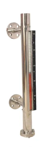
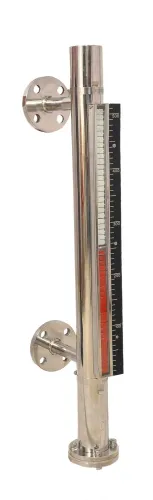
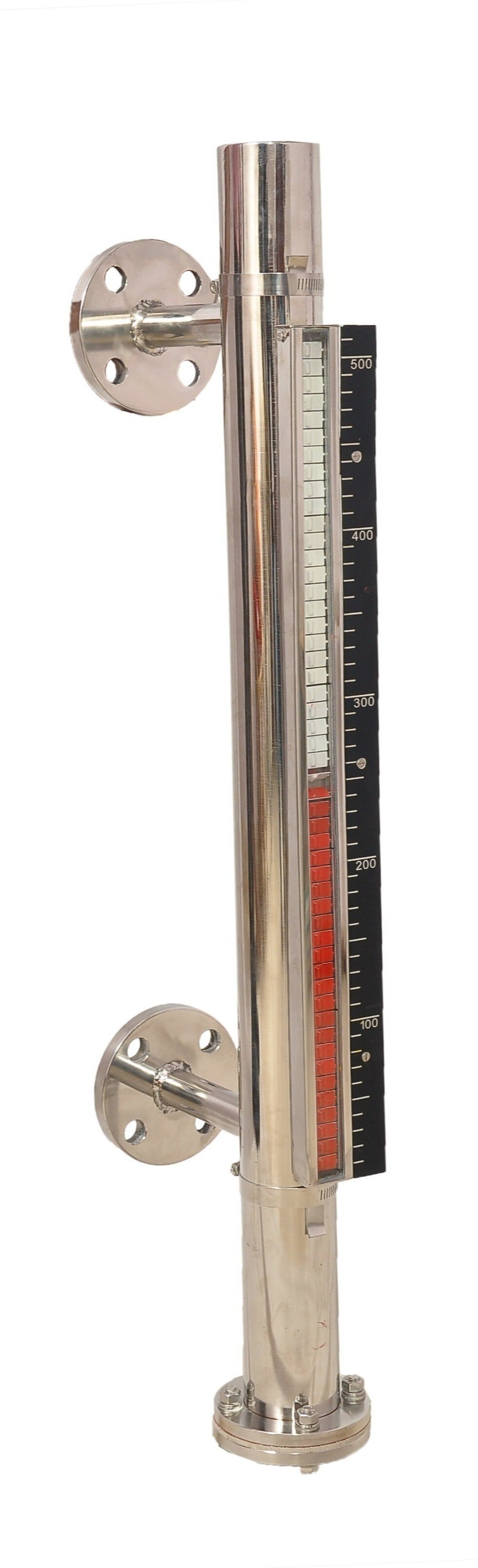
| Magnetic level gauge | Local continuous visual reading | Low electronics maintenance; visible at the tank; suits clean compatible liquids |
| Tubular glass gauge | Local continuous visual reading | Needs cleaning and glass inspection; visible nearby; unsuitable where breakage or corrosive service dominates |
| Float-and-board indicator | Continuous mechanical indication over distance | Little electronics; pulley and rope maintenance; suits large atmospheric tanks |
| Hydrostatic transmitter | Remote continuous value | Density-dependent; pressure-port maintenance; suits accessible liquid service |
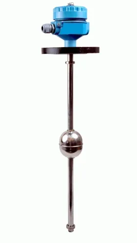
| Float transmitter | Continuous remote value | Moving-part maintenance; density and turbulence affect performance; suits compatible tanks |
| Point-level switch | One or more alarm points, not a level trend | Simple but requires functional testing; suits overfill or low-level protection |
A digital level indicator panel is the wrong choice when a local visual gauge is enough for an unstaffed tank, no compatible continuous sensor exists, the panel exceeds the transmitter’s signal limit, or you need remote logging and control. Filpro Sensors Pvt Ltd can be considered after this comparison when specifying the arrangement.
What to verify before putting the panel into service
Before service, turn the installation into a documented check rather than trusting a plausible number on the digital liquid level indicator panel. Compare the digital liquid level indicator with a traceable reference or independent measurement at representative low, mid-range, and high levels; one-point checking can miss reversed scaling, nonlinear volume errors, and high-end saturation.
- Match the transmitter’s lower-range value, upper-range value, damping, sensor-failure convention, wiring polarity, and input type. A mismatch can produce a believable but incorrect level.
- If HART, Modbus, or another protocol runs alongside 4–20 mA, compare the analog display with the digital register, tank-map value, and SCADA tag. Verify addressing and scaling instead of assuming agreement.
- Test relay outputs, high and low alarms, alarm delays, pump interlocking, retransmission, data logging, and PLC or SCADA communications. The panel provides these functions only when the selected model includes the hardware and the wiring is configured for them.
- Configure input-loss, out-of-range, sensor-fault, communication-failure, and power-failure responses to show an invalid state. Do not let a failed or stale value remain as a credible last reading.
- For hazardous areas, assess the panel location, enclosure, power supply, barriers or isolators, cable routing, and certification as one system.
Record the following before routine operation:
| Check | What to verify | Failure exposed |
|---|---|---|
| Range and units | Low, mid, and high readings against reference | Reversed scaling or saturation |
| Tank mapping | Level-to-volume calculation at each test point | Nonlinear volume error |
| Alarms and controls | Thresholds, delays, relays, and pump interlock | Unsafe switching |
| Communications | Register, tag, retransmission, and logged value | Wrong address or stale data |
Frequently asked questions
What does a digital liquid level indicator panel add to a tank?
It provides a local view of measured level, units, alarm state, signal quality, diagnostic status, and whether the reading is live or held.
How should you read a digital tank level indicator panel during a tank check?
Confirm the displayed value and units, then check the alarm state, signal quality, diagnostic message, and live-or-held indication before recording the reading.
How does a digital level indicator panel change routine tank checks?
It lets operators check the measured level from an accessible location instead of climbing to the vessel, while making abnormal readings and sensor faults easier to spot.
How do you choose the panel, sensor, and display location together?
Match the sensor output and measurement range to the panel input, select clear units and alarm functions, and place the display where operators can read it safely.
What should you verify before putting the panel into service?
Verify calibration, wiring polarity, displayed units, alarm limits, loss-of-signal behavior, live-or-held indication, and agreement with an independent tank measurement.