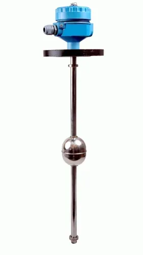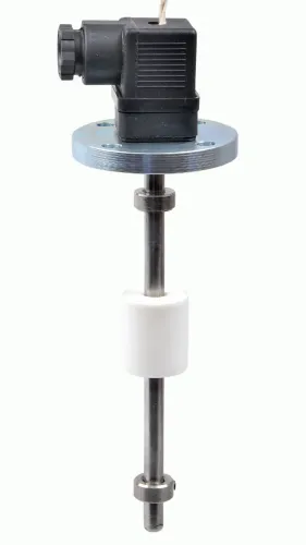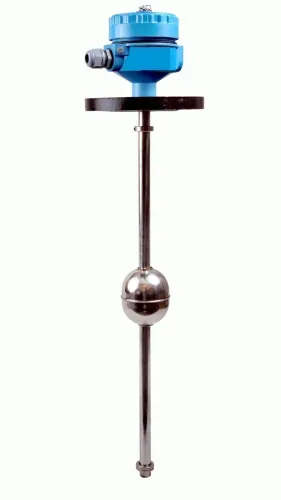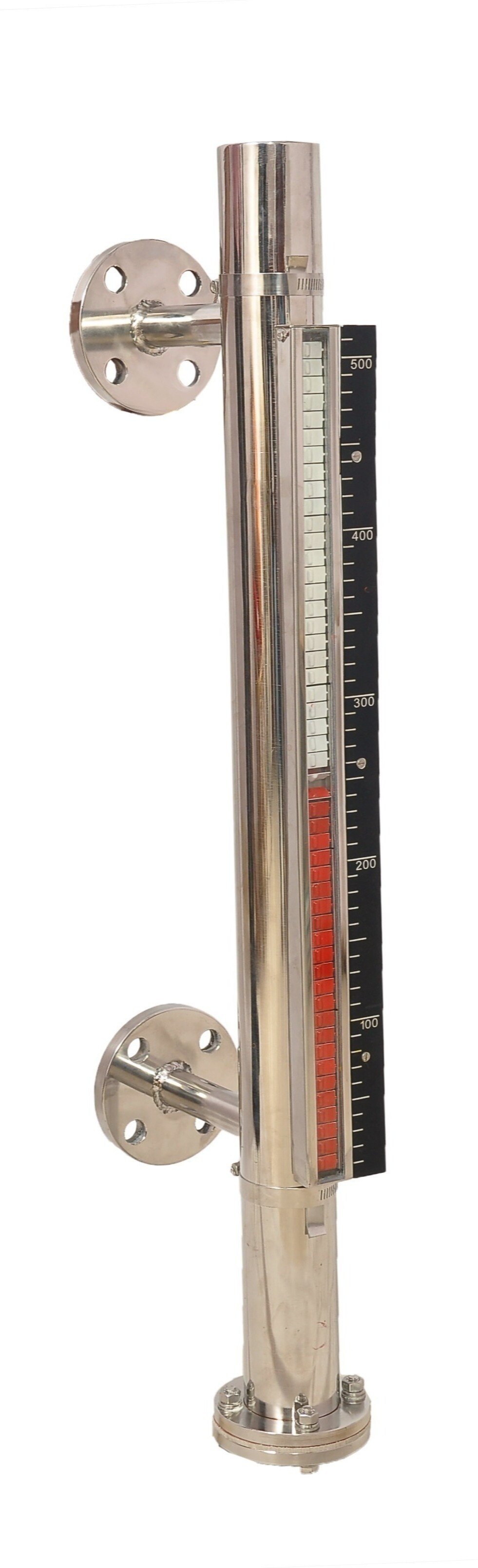
A local float, sight glass, or magnetic gauge shows what is happening at the tank, but it cannot send that reading to a control room by itself. By matching the sensing method, electrical output, communications path, scaling, and alarm rules, you can build a system that reports level remotely without confusing a real low level with stale or failed data.
Key takeaways
- A local gauge needs a separate sensor and transmitter to send level data remotely.
- Use a 4–20 mA output for direct PLC connections and digital protocols for richer diagnostics.
- Match the sensor to tank geometry, liquid properties, temperature and installation conditions.
- Test signal wiring, scaling, alarms and communications before relying on remote readings.
How a local level indication becomes a remote reading
An indicator at the tank becomes a level indicator for remote monitoring only when an added sensing element measures level and sends a signal to receiving equipment. A local visual gauge shows liquid at the vessel; it does not transmit that reading by itself.
- Add a continuous transmitter, such as a 4–20 mA unit, or a reed-switch, magnetostrictive, wireless, or camera-based sensor. A stuck float, blocked chamber, incorrect density selection, or misalignment can make the local indication disagree with the remote value.
- Connect the signal to a PLC, RTU, data logger, SCADA system, or wireless gateway, then send it to a dashboard with alarms and historical storage.
- Give the system tank geometry or a strapping table, plus density and temperature when needed. Level percentage alone produces incorrect inventory in horizontal, spherical, dished, or irregular tanks.
- In hazardous areas, match the transmitter, cable, glands, barriers or isolators, enclosure, power supply, and installation method to the protection concept and gas or dust classification.
| Output | Equipment and installation | Best use |
|---|---|---|
| 4–20 mA | Two-wire transmitter and configured receiver; treat 3.6 mA and below or 21 mA and above as faults, with 3.8–20.5 mA as the normal range | Industrial monitoring |
| 0–5 V or 0–10 V | Voltage transmitter and compatible analog input | Short, simple connections |
| RS-485 with Modbus RTU | Twisted-pair cable, correct polarity, termination, grounding, unique addresses, and confirmed baud rate and protocol | Multi-device networks |
| Point switch | Discrete input or wireless contact | Set-point alarms, not continuous trending |
Which output should connect to the PLC or gateway?
Choose the output by matching the sensor’s electrical signal and protocol to the PLC or gateway input. A 0–10 V signal connected to a current input produces an invalid reading, while an RS-485 level sensor remains silent until its wiring, address, baud rate, and protocol match.
| Option | What you connect | When to choose it |
|---|---|---|
| 0–5 V level output | PLC analog voltage input; scale 0 V and 5 V to empty and full | Use for short, simple point-to-point wiring when the receiver explicitly accepts 0–5 V |
| 0–10 V level output | PLC analog voltage input; scale 0 V and 10 V to empty and full | Use when the receiver accepts 0–10 V and cable noise or ground offsets are controlled |
| RS-485 with Modbus RTU | PLC serial port or RS-485 gateway; configure device address and registers | Use for multiple instruments, longer field wiring, digital diagnostics, or fewer analog input cards |
| Networked output, such as Modbus TCP or EtherNet/IP | Ethernet switch, PLC, or industrial gateway | Use when the plant already has a documented industrial network, IP plan, and access controls |
Voltage outputs need correct polarity, shared reference, and cable shielding; voltage drop and electrical noise can distort a distant reading. For RS-485, use twisted-pair cable, confirm A/B polarity, fit termination at the two bus ends, and plan grounding before installation.
Modbus RTU level monitoring also requires register mapping and a communications-loss alarm, so stale data cannot appear to be a steady tank level.
How the receiving system turns a signal into usable level data
The receiving system turns a signal into usable data through level transmitter scaling: it maps the raw 4–20 mA value or decoded digital register into engineering units such as millimetres, metres, or percentage.
The PLC checks whether the value is within its configured range, assigns a quality status, and passes valid data to SCADA or a gateway. A point switch produces a state—open or closed—not a continuous level value.
To calculate tank inventory, configure:
- Tank geometry or a strapping table that converts height into volume
- Product density and temperature when the result must be mass rather than volume
A linear percentage is not a reliable volume estimate for a horizontal, spherical, dished, or irregular tank. The control system applies the configured conversion and stores the result in the SCADA level history, allowing you to review trends, filling rates, usage, and unexplained changes.
Level alarm logic compares the calculated value with limits such as high, low, high-high, or low-low. Add a delay or persistence time so pump cycling and surface movement do not create nuisance alarms, then add hysteresis so an alarm does not repeatedly clear and return near its threshold.
Mark out-of-range current, failed device diagnostics, and invalid digital data as sensor faults. Raise a separate communications-loss alarm, because an unchanged displayed level can be stale data. Require acknowledgement for alarms that need operator action.
How to match the sensing method to the tank and liquid
Choose the sensing method by matching the tank geometry, liquid properties and installation conditions. A level indicator for remote monitoring needs an electronic sensing element and a compatible signal path; a sight glass or float-and-board alone only shows level locally.
| Option | Choose it when | Check before remote connection |
|---|---|---|
| Ultrasonic | You need non-contact ultrasonic level monitoring on water, wastewater or compatible chemicals. | Foam, vapour, condensation, agitators and a narrow or obstructed nozzle can create false echoes. |
| Hydrostatic | The tank is vented and the liquid has a stable density. | Enter the actual density, protect the diaphragm from sediment, and compensate for a pressurised or sealed vessel. |
| Fuel probe | You need fuel level monitoring in a vehicle tank or generator day tank. | Match probe length to tank depth and account for sloshing, baffles, grounding and fuel compatibility. |
| Magnetic gauge with transmitter | You want a clear local scale plus a remote signal on a pressurised tank. | A stuck float, blocked chamber, wrong density selection or transmitter misalignment can make the local and remote readings disagree. |
| Radar or point switch | Radar suits vapour, foam or long-range measurement; a point switch suits one high- or low-level alarm. | A switch cannot provide inventory trends, while radar requires correct antenna placement and configuration. |
For hazardous areas, verify the complete loop: instrument, barrier or isolator, cable glands, enclosure, power supply and installation method. Filpro Sensors Pvt Ltd can help you check probe length, liquid density, mounting and signal compatibility before specifying a transmitter.
Related products
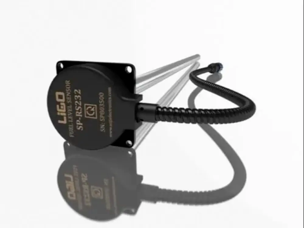 | Level Sensor Ligo fuel sensor for monitoring Diesel and Petrol level in vehicle fuel tanks and DG sets. View product → |
 | Level Transmitter Ultrasonic Level Sensor is a non-contact ultrasonic continuous level measurement product based on sound technology. View product → |
What makes a remote level system dependable in operation
Dependable wireless level monitoring begins with a power and failure plan, not the dashboard. Size the sensor battery for the transmission interval, coldest operating temperature, signal retries, and expected service period; power the gateway continuously where possible and alarm on low battery, lost communications, and stale data.
Configure the receiving system to distinguish a valid low reading from a transmitter fault: NAMUR NE 43 practice commonly treats about 3.6 mA and below, or 21 mA and above, as failure indications, with measurement between about 3.8 and 20.5 mA.
Use the instrument according to the job:
| Role | What it provides | What it cannot provide |
|---|---|---|
| Point level switch | A discrete alarm when level crosses one set point | Continuous trend or several software thresholds |
| Continuous transmitter | Level, rate of change, inventory estimates, and multiple alarm thresholds | Independent safety shutdown by itself |
| Monitoring transmitter | A remote tank level alarm through PLC, SCADA, or cloud logic | SIL-rated overfill protection |
Before commissioning, verify these installation points:
- Confirm nozzle position, tank geometry, obstructions, agitators, buildup, and radar echoes; a numerical reading does not prove a good installation.
- For hazardous-area level monitoring, match the transmitter, barriers or isolators, glands, enclosure, wiring, power supply, and installation practice to the gas or dust classification and protection concept.
- Treat overfill protection as a separate safety function under IEC 61511 where applicable, with suitable sensors, final elements, independence, proof testing, and lifecycle control.
Frequently asked questions
How does a local level indication become a remote reading?
A sensing element measures the liquid level, a transmitter converts it into an electrical signal, and a PLC or gateway receives the signal.
Which output should connect to a PLC or gateway?
Use a 4–20 mA output for a straightforward PLC input; use HART or a digital network when you need diagnostics and additional data.
How does the receiving system turn a signal into usable level data?
The PLC or gateway scales the signal against the configured empty and full points, then applies units, alarms and communications settings.
How do you match the sensing method to the tank and liquid?
Check tank shape, measurement range, liquid conductivity, vapour, foam, temperature, pressure and obstructions before selecting the sensor.
What makes a remote level system dependable?
Correct installation, shielded and correctly terminated wiring, accurate scaling, tested alarms, stable communications and a maintenance plan improve reliability.
Related product
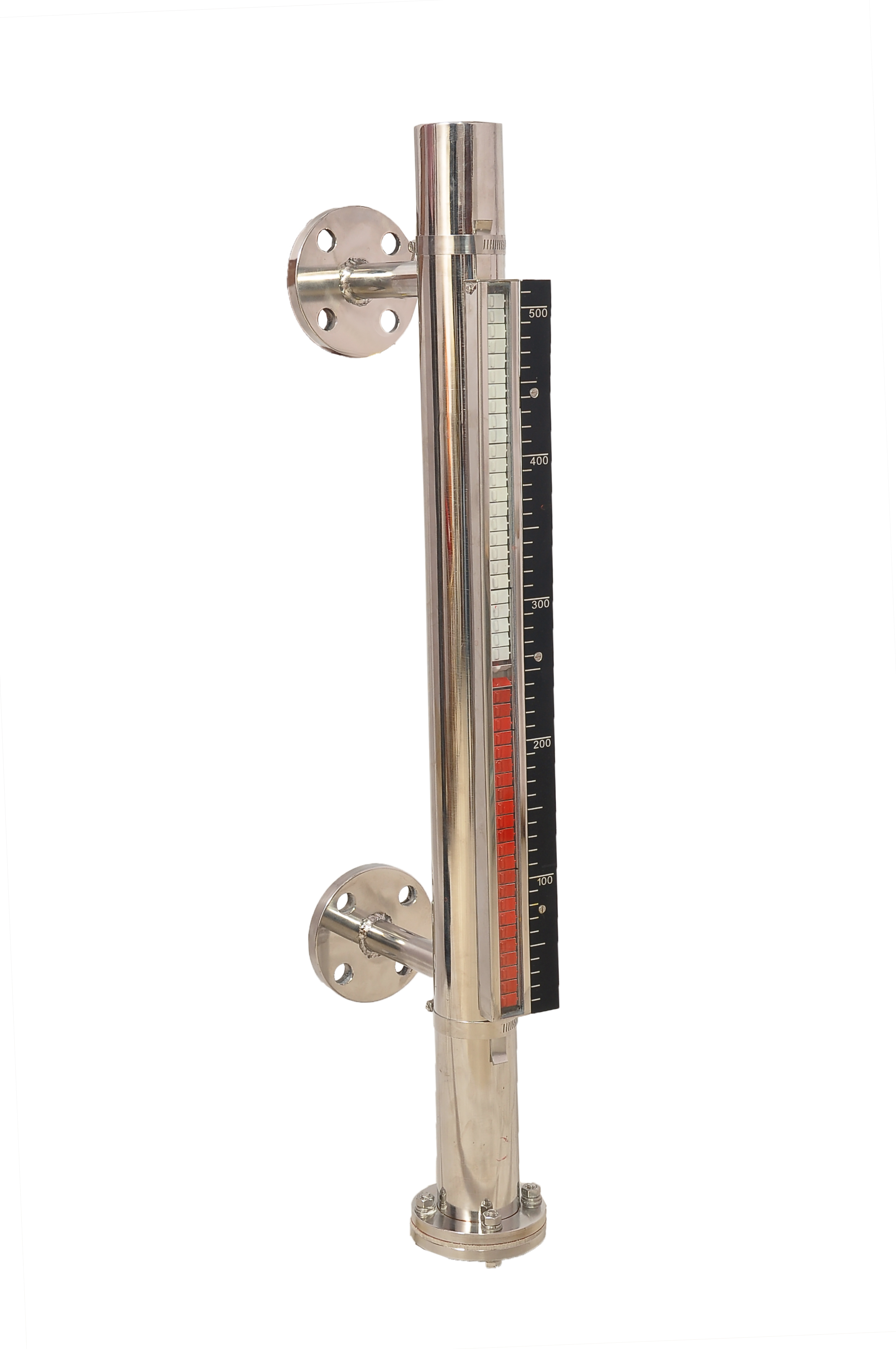 | Level Gauge FILPRO offers Magnetic Level Indicator provides clear, high clarity indication of liquid level. View product → |