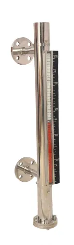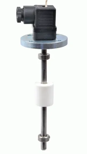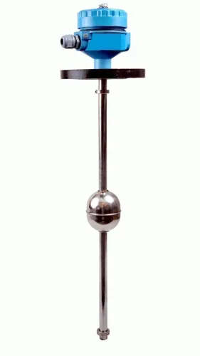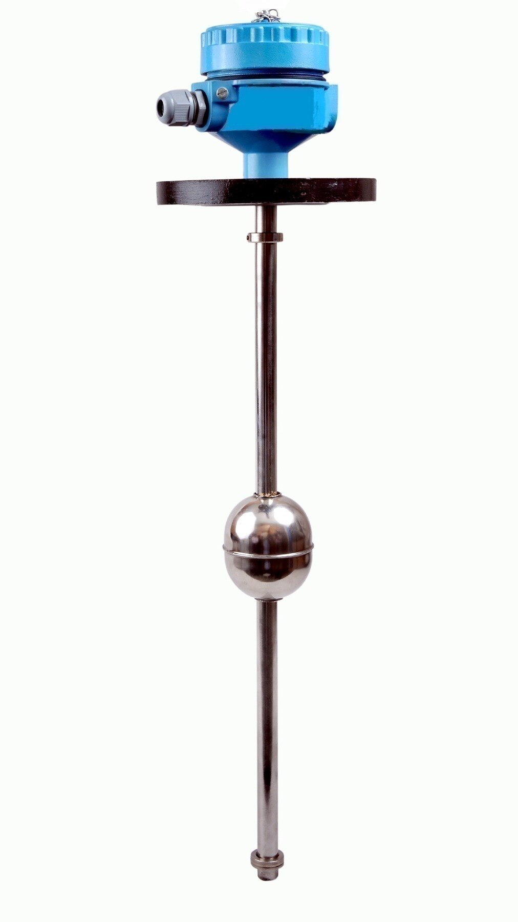
A pump can lose its liquid supply even while its motor continues running, causing overheating, seal damage, cavitation or impeller wear. You will learn how to position the switch, wire its signal, set a stable trip point and test the protection without confusing low-level shutdown with overflow control or automatic pump operation.
Key takeaways
- Place the low-level switch above the pump suction inlet.
- Use a normally closed contact to de-energise the pump on low level.
- Add a time delay or hysteresis to prevent rapid pump cycling.
- Test the complete shutdown circuit before putting the pump into service.
How the low-level switch stops a pump before the suction runs dry
A liquid level switch for pumps changes state when the liquid crosses a defined elevation. As the level falls, a float drops, a displacer moves, or electrodes lose their conductive path; that mechanical or electrical action changes the switch contact.
The switch normally controls a relay, contactor, motor starter, PLC input, pump controller, or VFD enable input—not the pump motor’s full current.
1. Set the low-level trip above the pump’s minimum submergence requirement. Include the outlet shape, vortex risk, turbulence, and the switch’s differential; placing the trip at the tank bottom can leave the suction uncovered.
2. Wire a normally closed control contact in series with the contactor coil or starter circuit. Above the setpoint, the contact remains closed and the coil can run the pump; when the level falls, the contact opens, the coil de-energises, and the motor contacts disconnect power.
3. For a normally open switch, use the contact to energise an interposing relay or send a low-level signal to a PLC or VFD. Program that signal to remove the run command and latch an alarm until an operator resets it.
4. Check the switch’s voltage, continuous current, and inductive-load ratings. A liquid level switch for tanks may provide high-level alarm or fill control, but one switch supplies only one switching point.
This trip does not detect every starvation fault. A vortex, blocked suction line, closed valve, lost prime, or air entering above the setpoint can still damage a pump. Combine low-level protection with motor overload protection; add flow, suction-pressure, phase-loss, seal-leakage, or temperature protection when the installation needs it.
Choose the contact function and connect it to the control circuit
Choose an NC permissive contact for low-level shutdown, wired in series with the contactor coil, motor-starter circuit, VFD enable, or pump-controller run permissive. The circuit remains energised while the level is safe; low level, broken wiring, or lost control power removes the run command instead of silently allowing operation.
| Function | Preferred contact arrangement | Control action |
|---|---|---|
| Low-level shutdown | NC, de-energize-to-trip permissive | Opens the run circuit or removes the VFD enable |
| Overflow control | NO contact that closes at high level | Starts an inlet pump, closes a valve, or energises an overflow alarm |
| Pump start/stop | Separate level points with relay or PLC logic | Starts at one level and stops at another |
| Alarm | NO for a high-level alarm, or supervised NC for fail-safe fault indication | Operates a beacon, horn, message, or shutdown relay |
A single liquid level switch for pumps provides only one switching point. Use two switches for start and stop, or use a continuous sensor with a liquid level controller for pumps; program hysteresis, start delay, minimum off-time, and restart permission so turbulence does not chatter the contactor or repeatedly restart the pump.
- Connect the switch to a relay coil, motor starter, PLC input, or VFD control terminal unless its contact rating covers the circuit’s voltage, current, and inductive load.
- Confirm whether “high” means pump start or pump stop: a sump-emptying pump normally starts at high level and stops at low level.
- Require a manual reset or permissive check after a low-level trip when automatic restart could create a hazard.
Set the sensor above the suction inlet and prevent rapid cycling
Install the low-level probe or float above the suction inlet, not at the tank bottom. Set its trip elevation high enough to maintain the pump’s required minimum submergence and cover the level lost while the pump stops.
A liquid level switch for pumps detects only a point elevation; it cannot confirm suction flow or reveal a vortex.
Before fixing the setpoint, account for:
- Minimum submergence: use the pump manufacturer’s specified depth above the inlet, then add a margin for the tank’s outlet shape and drawdown pattern.
- Stopping time: allow for the liquid volume removed between the low-level trip and motor stoppage, including contactor or VFD delay.
- Turbulence: keep the sensor away from the outlet jet, vortex zone and strong return flow. Fit a stilling tube or baffle when the surface surges.
- Hysteresis: include the switch’s differential between falling-level trip and rising-level reset so the pump does not restart beside the same threshold.
Use separate start and stop elevations when automatic operation is required. A minimum off-time prevents immediate restart after a trip, while a minimum run-time prevents a pump from stopping as soon as the surface ripples. Add a start delay if filling turbulence causes false resets.
A liquid level switch for tanks can serve as the low-level cutout, but one switch cannot also provide independent start, high-level alarm and overflow control. Use multiple setpoints or a continuous transmitter for those functions.
Commission the shutdown and find faults that defeat it
Prove the shutdown under a controlled low-level condition, not by assuming the liquid level switch for pumps is wired correctly. Record the switch state, contactor or relay state, motor current, and pump response during the test.
- Stop the pump and inspect the float, probe, mounting bracket, cable, and chamber. Remove sludge, confirm free movement, and check that the switch sits at the documented trip elevation.
- Lower the liquid below the shutdown point, or lift the float and simulate the trip with the approved test method. Confirm the contact changes state at the setpoint.
- Start the pump from its normal control station. The contactor, motor starter, relay, or VFD enable must de-energise, and the pump must stop. Confirm that a PLC or alarm records the low-level trip.
- Restore the level, reset the alarm, and verify that the pump does not restart unless the liquid level controller for pumps receives its configured start conditions.
A pump can remain energised when a bypass link is fitted, a relay contact is welded, the starter is mechanically stuck, or the PLC/VFD logic is forced into run. A broken wire, failed relay coil, incorrect input polarity, or loss of control power can also defeat the intended fail-safe response.
The pump can still be starved while the switch remains satisfied. Check for a vortex, closed discharge or suction valve, blocked or undersized suction pipe, lost prime, air entrainment, and a sensor mounted too close to the outlet. A level switch does not replace overload protection, flow sensing, suction-pressure monitoring, or seal-temperature protection.
Match the sensing technology and protection layers to the installation
Choose the sensor by the liquid, tank geometry and failure you need to detect. A liquid level switch for tanks gives one elevation; separate start, stop, overflow and alarm points require multiple switches or a transmitter with control logic. The sensor normally signals a relay, starter or PLC, not the pump motor directly.
| Option | What it detects well | Main limitation |
|---|---|---|
| Float | A rising or falling level in clean or mildly dirty liquid | Turbulence, solids and mechanical wear can cause sticking |
| Conductive | Aqueous liquids that complete an electrical circuit between electrodes | It will not work reliably in oil, deionised water or liquids that coat the electrodes |
| Capacitive | Point level in conductive or non-conductive liquids without moving parts | Foam, buildup and changes in dielectric properties can shift the switching point |
| Non-contact ultrasonic or radar | A point level without wetted components in corrosive or hard-to-access tanks | Foam, vapour, internals and a poor aiming path can produce a false level |
When specifying a side-mounted device from Filpro Sensors Pvt Ltd, give the supplier the liquid’s conductivity, temperature, viscosity, solids content and tank dimensions; these details determine whether the sensing face stays reliable.
A liquid level controller for pumps adds the protection logic a bare switch lacks. Keep these layers in the design:
- Motor overload and short-circuit protection
- Phase-loss or phase-sequence protection for three-phase motors
- Suction pressure, flow, or VFD underload protection for a blocked line, closed valve, vortex or lost prime
- A restart delay, recovered-level permissive and manual reset where automatic restarting is unsafe
A level switch cannot detect every starved-pump condition. Configure the controller to trip on any independent fault and record which protection opened the circuit.
Related products
 | Level Switch Filpro offers most reliable, cost effective Side Mounted Level Switch for point level sensing. View product → |
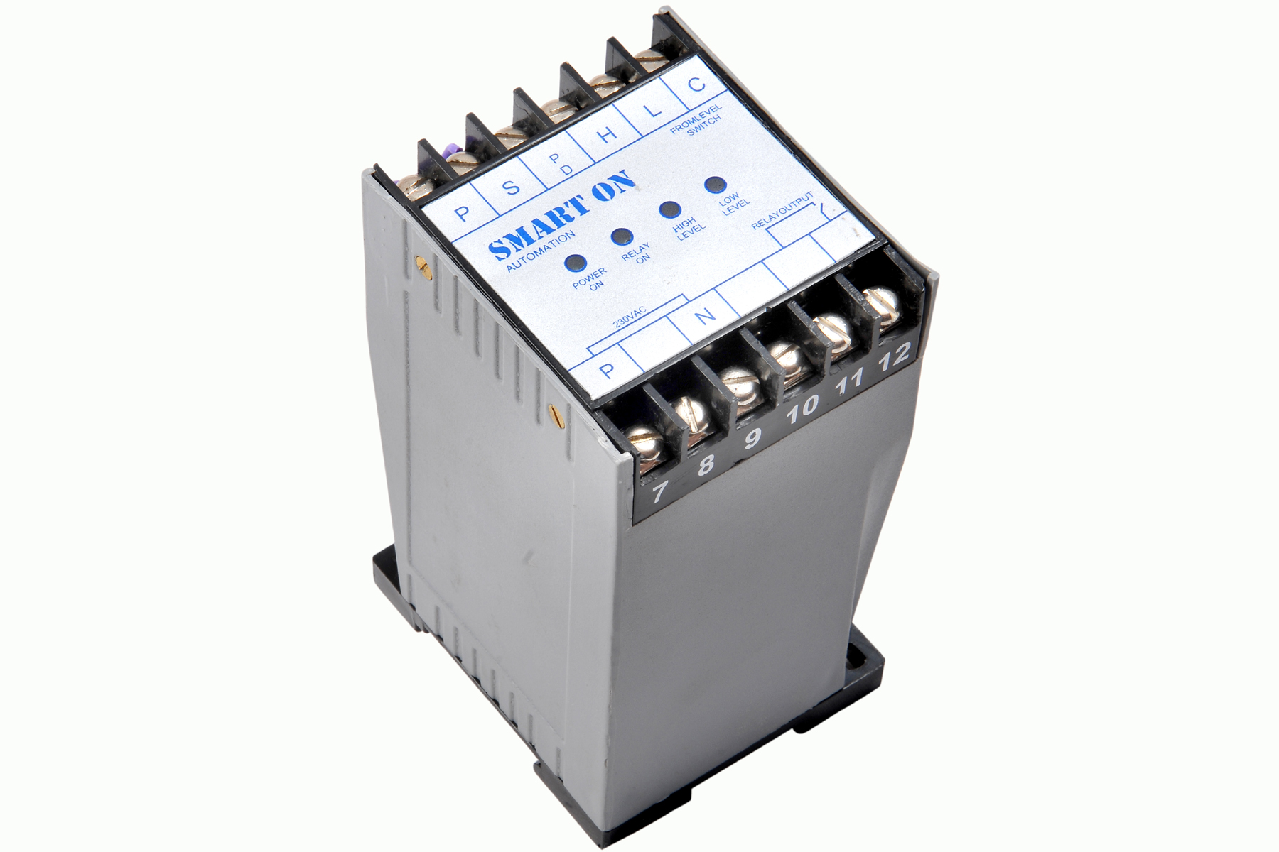 | Controller Filpro Sensors Pvt Ltd manufactures industrial Level Controller (Smart On) to automatically start & stop the pump. View product → |
Frequently asked questions
How does a low-level switch stop a pump before the suction runs dry?
The switch changes state as liquid falls below a defined elevation, opening or closing the control circuit that runs the pump. Set it above the suction inlet so the pump stops before it draws air.
Which contact function should you use for pump dry-run protection?
Choose the contact arrangement that de-energises the pump when the liquid is low or when the switch circuit loses power. Confirm the contact state with a meter and wire it into the pump control circuit.
How do you prevent a liquid level switch from causing rapid cycling?
Set enough separation between the pump-stop and pump-start levels, or add electrical hysteresis or a time delay. Commission the switch while observing the actual tank level and pump response.
What should you check when a pump does not shut down at low level?
Check the switch elevation, float or electrode movement, contact state, wiring, control relay, bypass links and alarm logic. Test the shutdown with the pump running instead of relying only on a continuity check.
Related products
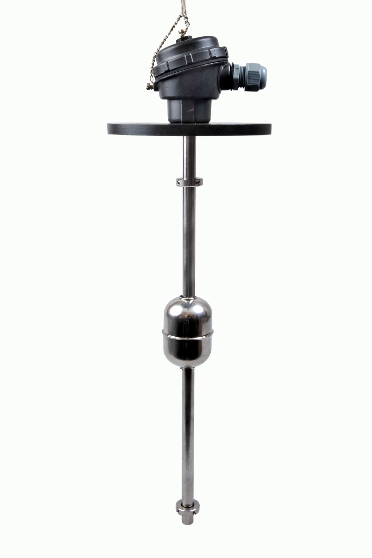 | Level Switch The Magnetic Level Switch consists of the non-abrasive float carrying permanent magnet and non-ferrous stem carrying one. View product → |
 | Level Transmitter Float Level Transmitters Are Ideal For Continuous Level Monitoring In Water, Diesel, Chemical And Oils For Accurate Level Measurement. View product → |