A tank switch does not power a pump by itself: it sends a discrete level state to a controller, which interprets that state and changes a relay contact. By the end, you will be able to trace the signal from sensor to load, choose start and stop logic, select fail-safe contact behavior, and decide when a contactor is necessary.
Key takeaways
- The sensor supplies a level signal; the relay switches the external load.
- Use normally closed logic when a broken control circuit must trigger a fault response.
- Set separate start and stop levels to prevent rapid pump cycling.
- Drive a contactor for motor loads instead of switching a pump directly.
What happens between the level sensor and the final load?
A level controller with relay output is a two-stage device: it interprets a level signal, then switches power to another device. The relay is the switching interface; it does not measure liquid level.
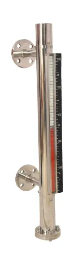
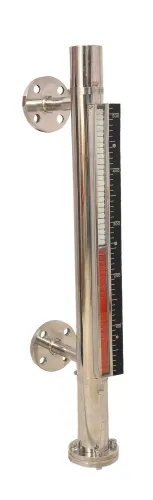
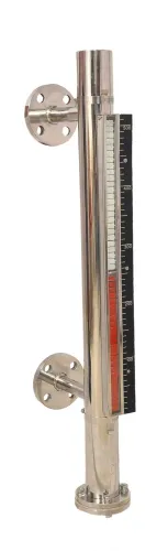
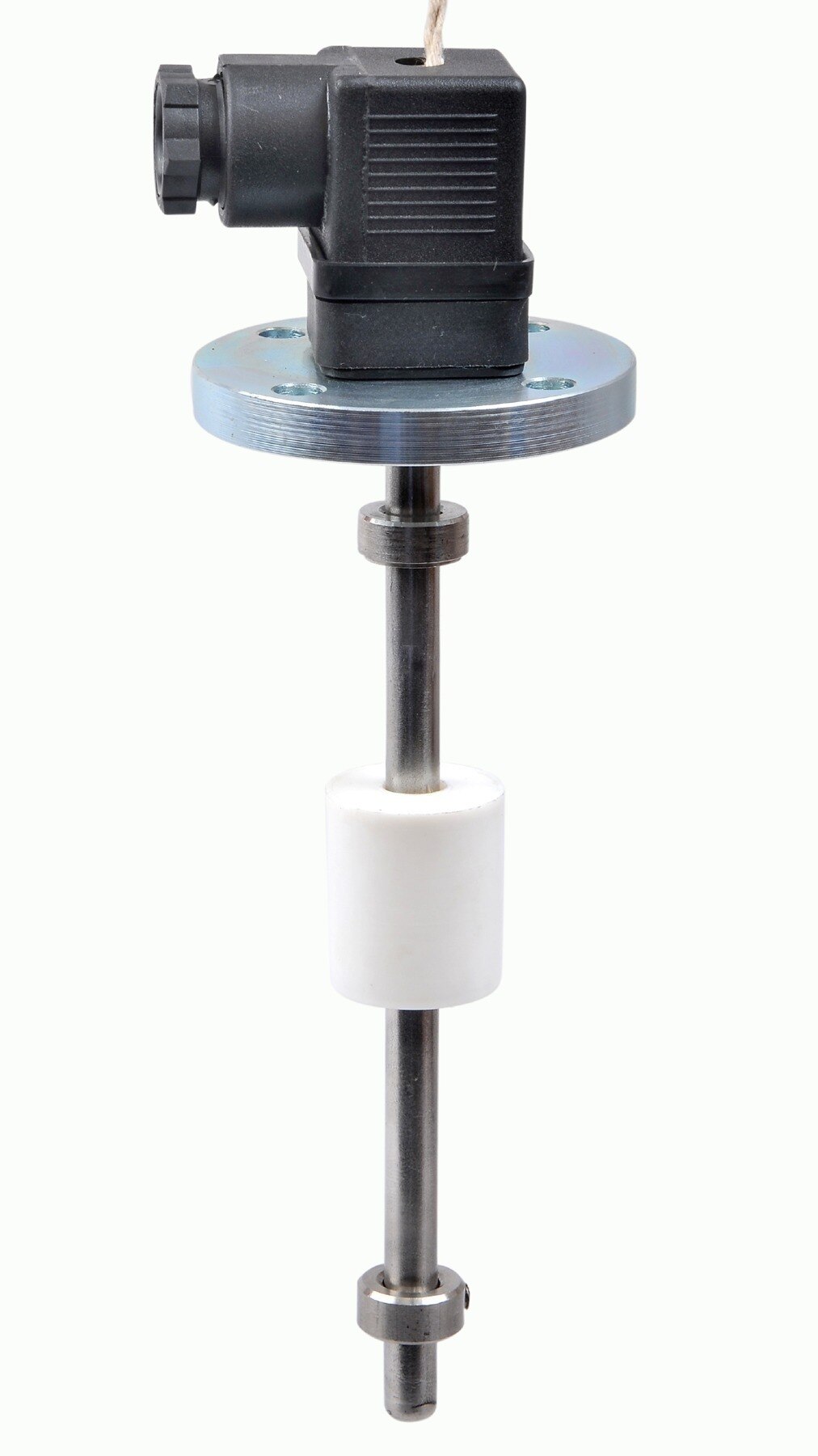
1. A float switch, magnetic float switch, cable float switch, or side-mounted switch creates an open or closed circuit as liquid reaches its operating point. A conductive probe instead creates a conductive state when liquid bridges its electrodes.
2. The controller input reads that state. Use a discrete-input controller for these devices; a 4–20 mA input expects a continuous current signal and scales it to level, so the two input types are not interchangeable.
3. Configured logic compares the input with the required condition, such as “start the pump at low level” or “alarm at high level.” The controller then energises or de-energises the relay coil.
4. The relay contacts switch the final circuit: a motor starter, contactor, solenoid valve, alarm circuit, or interposing relay. A changeover relay provides common, normally open, and normally closed terminals, but you must choose whether the load operates with the coil energised or de-energised.
A relay output is normally an isolated dry contact. It does not supply control voltage, so verify whether you need an external supply and whether its voltage and current suit the contact. A powered transistor or solid-state output is different: the documentation must state how it supplies or switches the load.
Test the complete chain at actual trip levels, including wiring, relay state, actuator response, alarms, and recovery after power failure.
How do normally open, normally closed, and fail-safe relay circuits behave?
A level controller with relay output changes a relay’s contacts, but terminal labels describe the coil’s unpowered state—not a guaranteed safety function. In an SPDT (changeover) relay, COM is the moving terminal; NC connects to COM when the relay is de-energised, and NO connects to COM when it is energised.
| Relay state | COM–NC | COM–NO |
|---|---|---|
| De-energised | Closed | Open |
| Energised | Open | Closed |
Use the contact pair that matches the action you want. A low-level pump-control circuit might energise the relay to start filling, then de-energise it at the high threshold; hysteresis, such as start at 30% and stop at 70%, prevents chatter.
A high-level alarm might use the opposite logic, energising a horn or trip circuit when the high threshold is reached.
NC does not mean fail-safe. De-energise-to-trip wiring makes the alarm or shutdown condition occur when the relay loses power, a sensor wire breaks, or the controller faults; the complete circuit must be designed and tested for that result.
A circuit that runs a load only while the relay is energised instead stops on power loss, which can be right for a pump but wrong for an alarm.
Specify separately whether each function should:
- Reset automatically when level returns inside the control band, as normal pump control often does.
- Latch a high-level alarm until someone investigates and presses a manual reset.
- Be tested at trip levels for relay state, broken wiring, actuator response, alarm annunciation, and power-loss recovery.
How are pump start, stop, and alarm levels created?
Pump start and stop levels come from two thresholds separated by hysteresis, also called differential or deadband. In a filling application, the relay starts the pump when level falls to 30% and stops it at 70%; for draining, it starts at 70% and stops at 30%.
The gap prevents waves, float bounce, or measurement noise from chattering the relay state.
1. Choose the switching arrangement. One float can provide simple on/off action at a single point, but it cannot independently define start and stop points. Use two floats when separate start and stop levels are required, or configure two thresholds from a continuous sensor.
2. Match the input to the vessel. A magnetic float switch suits guided vertical movement. A cable float switch hangs in the tank and changes state as it tilts. A side-mounted switch provides a fixed wall setpoint, while conductive probes detect liquid reaching exposed electrodes.
3. Set the level controller with relay output for one job: fill, drain, high alarm, or low alarm. Separate high and low alarms, or simultaneous fill and drain control, need additional relay outputs or independently configurable channels.
4. Allow for turbulence, foam, splashing, and sensor uncertainty. A narrow deadband causes repeated starts; excessive separation permits unsafe level excursions. Input filtering or a time delay can suppress bounce, but too much delay can prolong overfill or dry-run conditions. Alarm latching and manual reset may be needed even when normal pump control resets automatically.
When should the relay drive a contactor instead of the pump motor?
Use a contactor whenever the pump motor’s load exceeds the level controller relay’s rating for that specific load. A published rating for a resistive AC load does not transfer unchanged to a motor, solenoid, or contactor coil. Motor starting current can exceed the relay’s permissible switching capacity even when the pump’s running current appears acceptable.
A level controller with relay output should then operate the contactor coil or an interposing relay, while the contactor switches the pump’s power circuit. The concept is: controller relay contacts to the protected coil circuit; contactor main contacts to the motor supply; overload protection in the motor circuit.
Confirm the coil voltage and suppress its inductive switching transient.
Before approving direct switching or a control-circuit design, check:
- The relay datasheet’s rating for the actual load type, not only its resistive AC figure.
- Starting or inrush current, switching voltage, duty cycle, and electrical endurance.
- A correctly rated fuse or circuit breaker for the control and power circuits.
- Motor overload protection set for the motor and installation.
- Protective earthing and an emergency-stop circuit where the installation requires one.
- Contact suppression for the contactor coil or solenoid.
- A response to welded contacts, such as a feedback or auxiliary-contact check; the controller does not provide this protection automatically.
- De-energize-to-trip behaviour after power loss, broken wiring, or controller failure, verified by testing the complete circuit.
How do you match the input type and prove the complete system works?
1. Match the controller input to the sensor before wiring. A float or probe is a discrete switch: it reports open or closed, or conductive or non-conductive. A 4–20 mA transmitter supplies a scaled continuous signal that the controller converts into level thresholds.
Substituting one for the other can leave the controller permanently full, permanently empty, or unable to detect a trip.
2. Check the sensing method against the installation. For conductive probes, confirm liquid conductivity, electrode coating, reference-electrode grounding, and probe spacing; coating or poor grounding can create a false level. For floats, provide enough clearance for movement and protect the float from turbulence, restricted travel, bounce, and sticking.
Set filtering or delay only long enough to suppress false switching, because excessive delay can prolong overfill or dry-running.
3. Ask the supplier, including Filpro Sensors Pvt Ltd, to state the input type, contact arrangement, hysteresis range, delay or filtering settings, relay rating for your load, external supply requirements, and power-failure behaviour.
Check whether the relay is electromechanical or solid-state, and confirm that the specified voltage and current suit the starter, valve, alarm, or interposing relay.
4. Commission the complete chain at the actual low and high trip levels. Record the sensor state, controller indication, relay state, field-wiring continuity, starter or valve response, alarm annunciation, and actuator movement. Interrupt power, restore it, and verify the intended restart or safe-trip behaviour; then confirm contact recovery.
A normal display proves only the input path, not that the final process is safe.
Related product
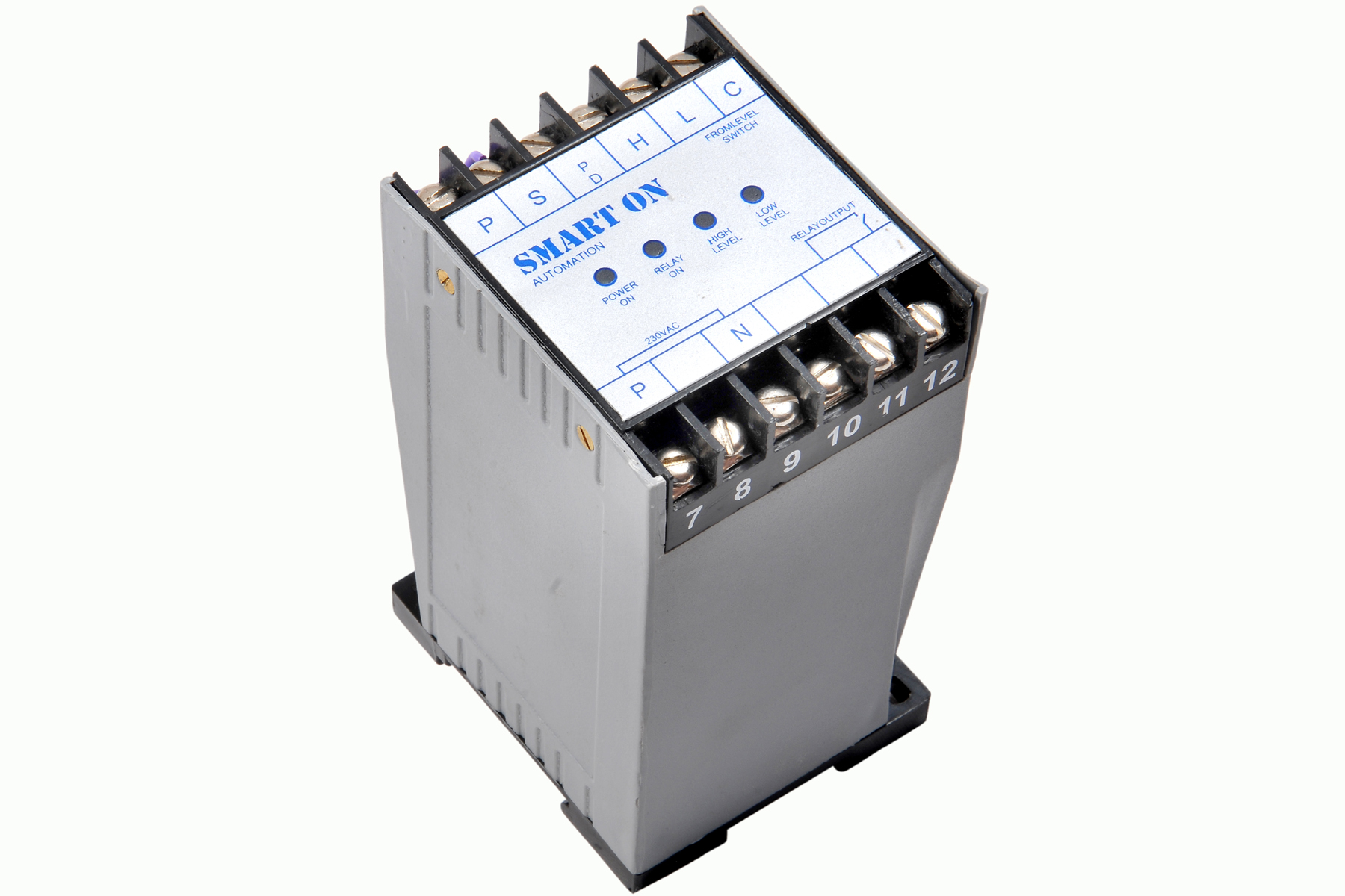 | Controller Filpro Sensors Pvt Ltd manufactures industrial Level Controller (Smart On) to automatically start & stop the pump. View product → |
Frequently asked questions
What happens between the level sensor and the final load?
The sensor sends a level signal to the controller, which compares it with configured limits and energises or de-energises its relay contacts. Those contacts then switch an alarm, solenoid, contactor coil, or other load.
How do normally open and normally closed relay circuits behave?
A normally open contact closes when the relay energises, while a normally closed contact opens. Choose the contact arrangement according to whether the load must run during a normal energised state or respond to loss of power as a fault.
How are pump start, stop, and alarm levels created?
Configure separate level thresholds or use separate sensors at the required elevations. The controller starts the pump at the high threshold, stops it at the low threshold, and activates an alarm at a defined high-high or low-low level.
When should a relay drive a contactor instead of the pump motor?
Use a contactor when the pump motor current, starting surge, voltage, or phase arrangement exceeds the controller relay rating. The controller then switches the contactor coil, while the contactor switches motor power.
How do you match the input type and prove the complete system works?
Match the controller input to the sensor output, such as a float switch, conductive probe, 4–20 mA transmitter, or voltage signal. Test simulated low and high levels, relay state, contactor operation, alarms, and recovery after power loss.