Start with the job the instrument must perform: show a local level, provide a continuous signal, trip an independent alarm, or control a pump. By the end, you will be able to match that function to a sensing technology, installation arrangement, control logic and purchase specification.
Key takeaways
- Choose local indication, continuous measurement, independent trip or automatic control first.
- Match radar, ultrasonic, float, hydrostatic or conductive sensing to the liquid and tank.
- Document viscosity, density, temperature, pressure, foam, vapour and corrosiveness before ordering.
- Specify mounting, alarm setpoints, fail state, output signal and controller logic.
Choose the measurement function before the instrument
Choose the device by the operating or protection function: a local reading, a continuous measurement, an independent trip, or automatic control. Tank level indicator selection starts here, not with accuracy or mounting style.
| Option | What it does | When it applies |
|---|---|---|
| Local indicator | Shows level at the tank | Operators need a visual reading |
| Point-level switch | Changes state at a high or low setpoint | Alarm, pump protection, or independent trip |
| Continuous transmitter | Sends a level value through 4–20 mA, HART, or fieldbus | Inventory, PLC or SCADA input, or process control |
| Controller | Applies logic to start, stop, alarm, or interlock equipment | Automatic filling, draining, or pump protection |
Tank level controller selection must separate the sensing element from the control function. A transmitter does not provide alarm voting, relay logic, deadband, manual override, dry-run protection, fail-safe action, or power-failure recovery unless separate control equipment does.
For a tank level switch selection, define the consequence of a missed trip before comparing nominal accuracy. Specify:
- High-high or low-low duty
- Normal output state and failure state
- Latching, reset, and proof-test requirements
- Switching voltage, current, and relay needs
API 2350 separates basic control, alarms, and independent overfill protection. A float or displacer suits simple liquids only when density, viscosity, turbulence, and mechanical freedom remain within its operating limits.
Match the sensing technology to the liquid and tank
Match the technology to the liquid, tank atmosphere and consequence of failure. Tank level indicator selection is not only about range: a clean water tank and a hot, foaming chemical tank demand different sensors.
| Technology | Fits the process | Main limitation |
|---|---|---|
| Float | Simple local indication or point switching in clean, low-viscosity liquids | Needs space to move; solids, sticky product and turbulence can jam it |
| Displacer | Continuous or point measurement where a chamber can isolate the sensing element | Apparent level changes when liquid density or interface conditions change |
| Conductive | High- or low-level switching in water-based, electrically conductive liquids | Does not work with oils or non-conductive liquids; coating can insulate the probe |
| Capacitive | Point or continuous measurement in liquids with a stable dielectric constant | Recheck clean and coated probe conditions; moisture, deposits and changing interfaces shift the signal |
| Ultrasonic | Non-contact measurement on calm, clean tanks with a clear gas space | Foam, vapour, condensation, dust, temperature gradients and turbulence can corrupt the echo |
| Radar | Non-contact measurement where vapour, pressure or temperature challenge sound-based instruments | Foam, internals and a poor mounting location can still create false echoes |
| Hydrostatic | Open or closed tanks where liquid density is stable and bottom pressure represents level | Density changes alter the reading; closed tanks need correct vapour-space pressure compensation |
For a level switch, define what happens on high level, low level, power loss and broken wiring. An energised relay or monitored circuit exposes faults; a de-energised relay can make a failed switch look healthy. For overfill protection, keep the independent protection device separate from the transmitter used for control.
Check the liquid properties before ordering
Check the liquid across its full operating range, not only its name. For tank level indicator selection, record density, viscosity, conductivity, foam, solids, corrosiveness and temperature at minimum and maximum conditions.
| Property | What to verify | What can go wrong |
|---|---|---|
| Density | Specific gravity at operating temperature | Float or displacer devices can miss trips or show the wrong level when buoyancy changes. |
| Viscosity | Flow resistance, especially during cold starts | Floats can move slowly, stick or fail to return after a level change. |
| Conductivity | Conductive or non-conductive liquid, plus dielectric constant | Capacitance probes can shift with moisture, coating or a changing product composition. |
| Foam | Foam depth, stability and gas-space vapour | Ultrasonic echoes can weaken or reflect from foam instead of the liquid surface. |
| Solids | Particle size, settling, sludge and product buildup | Probes can foul, floats can jam and switching points can become unreliable. |
| Corrosion | Compatibility with wetted metal, seals and coatings | Pitting or seal failure can create leaks and false signals. |
| Temperature | Liquid, vapour-space and cleaning temperatures | Electronics, seals and calibration can fail outside their rated range. |
A tank level switch selection guide should include clean and coated probe conditions, fill and drain rates, wave action, and the required normal and failure state. Specify whether loss of power, broken wiring or a failed instrument must create an alarm; a de-energised relay can hide that fault.
Specify the mounting point and measurement environment
Mount the device where the level is representative, accessible for inspection, and clear of the inlet jet, outlet vortex, agitator sweep, heating coils, and internal ladders.
For a point-level switch, set the elevation against the normal operating band, fill and drain rates, and required switching differential; placing it too close to the band can cause pump chatter.
| Device | Mounting point | Features that can cause false readings or unwanted operation |
|---|---|---|
| Local indicator | At a visible tank connection or in a tank level indicator panel | Poor viewing angle, blocked sight path, temperature outside the display rating, or an unrepresentative gauge connection |
| Point-level switch | At the defined high-high, high, low, or low-low trip elevation | Waves, foam, splashing, buildup, turbulence, and a fixed differential that causes short-cycling |
| Continuous transmitter | Where the sensing path remains clear across the measuring range | Nozzles, agitator blades, vapor, condensation, multiple reflections, and weak or false radar echoes |
Keep radar antennas away from obstructions and strong turbulence, then specify echo mapping during commissioning. Check whether foam, vapor, condensation, or product buildup will cover the sensing face or interrupt the intended echo path. For outdoor equipment, define ambient temperature, rain exposure, enclosure rating, and cable-entry orientation before ordering.
Define switch behaviour and controller logic
Define the required response before comparing instruments: the system must state what happens when level rises or falls, a pump fails, power disappears, or an unsafe condition appears. A transmitter providing 4–20 mA, HART or fieldbus data does not automatically provide controller logic, alarm voting, interlocks or fail-safe action.
A tank level controller selection guide should separate the sensing element from the control function. Tank level controller selection therefore includes the PLC, relay panel or dedicated controller that interprets the signal and commands equipment.
Specify these behaviours in the cause-and-effect document:
- Set pump start and stop points, with enough differential to prevent rapid cycling during waves or slow level changes.
- Define high-high and low-low actions, including alarm, pump shutdown, valve closure and whether the trip latches until a person resets it.
- Use permissives for low suction level, unavailable pump feedback, closed valves and other conditions that make starting unsafe.
- Choose the normal and failure state for every switch: high level, low level, broken wire, failed instrument and loss of power must not look identical.
- State whether a manual override is allowed, who can use it and which independent trip remains active during override.
- Define the post-failure action: hold outputs off, restart automatically after power returns, or require acknowledgement and a fresh permissive.
For tank level switch selection, a normally energised relay or monitored circuit exposes power and signal loss; a de-energised relay can leave a hazardous state looking healthy. Check relay voltage, switching current and whether the switch drives a pump directly or only sends an input to the control system.
For overfill protection, treat an independent high-high switch as a separate protection layer rather than relying on the control transmitter. API 2350 distinguishes basic process control, alarm and independent protection functions.
Turn the decision into a complete purchase specification
Turn the quotation into a complete purchase specification, not a product name. Ask the supplier to confirm these items in writing:
1. Measurement output and accuracy: local scale, 4–20 mA, HART or fieldbus; reference datum; calibrated range; display units; and effects of tank shape, turbulence, temperature and calibration on usable accuracy.
2. Switch duty: high-high or low-low setpoint, normal and failure state, normally open or normally closed contacts, latching, switching voltage and current, relay or isolator, proof-test method, and required safety function under API 2350. Use the tank level switch selection guide to document what loss of power, broken wire and failed instrument must indicate.
3. Electrical and controller details: supply voltage, loop-power budget, PLC or SCADA input, pump interlock, voting, deadband, permissives, manual override, restart after power loss and fail-safe action. A tank level controller selection must separate transmitter output from these control functions.
4. Panel specification: state whether the tank level indicator panel includes only a display or also isolation, alarm relays, event logging and communications; add enclosure rating, temperature, hazardous-area interface, alarm acknowledgement and loss-of-signal behaviour.
Filpro Sensors Pvt Ltd can review these requirements against its switch, transmitter and controller configurations before approval.
Related products
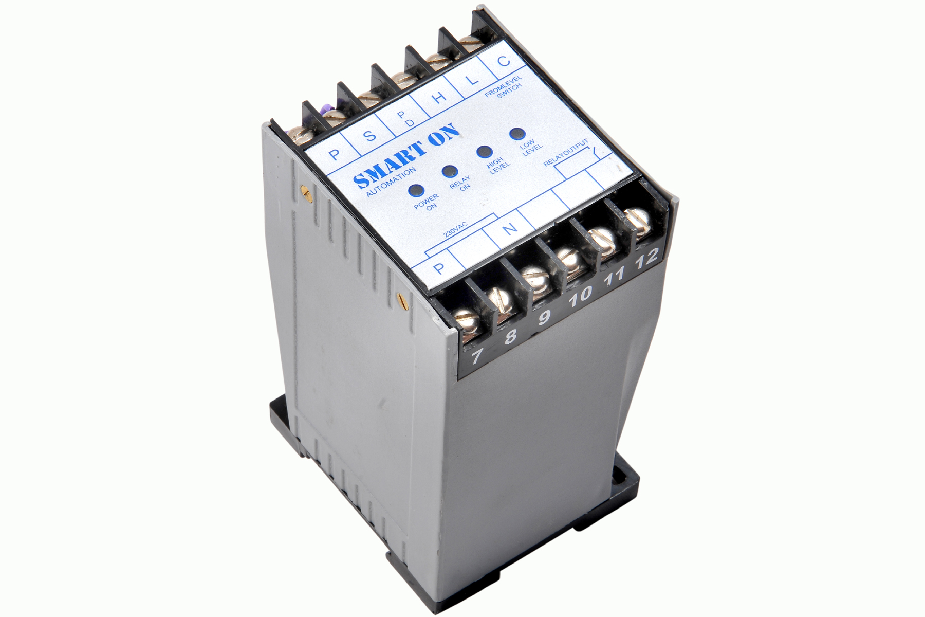 | Controller Filpro Sensors Pvt Ltd manufactures industrial Level Controller (Smart On) to automatically start & stop the pump. View product → |
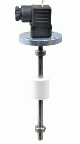
 | Level Switch Filpro offers most reliable, cost effective Side Mounted Level Switch for point level sensing. View product → |
Frequently asked questions
How do you choose between a tank level indicator, switch and controller?
Choose an indicator for local level reading, a switch for a discrete alarm or trip, and a controller for automatic actions such as pump start, stop or valve control.
Which sensing technology suits a tank liquid?
Match the technology to the liquid and tank: consider conductivity, viscosity, density, foam, vapour, temperature, pressure, agitation and obstructions before selecting the sensor.
What liquid properties must you provide for tank level switch selection?
Provide the liquid name, density or specific gravity, viscosity, conductivity, corrosiveness, temperature range, pressure, foam tendency and suspended solids.
What must a tank level controller purchase specification include?
State the measurement range, mounting point, process connection, materials, power supply, output signal, alarm setpoints, fail-safe behaviour and required control sequence.
Related products
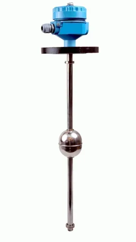
 | Level Transmitter Float Level Transmitters Are Ideal For Continuous Level Monitoring In Water, Diesel, Chemical And Oils For Accurate Level Measurement. View product → |
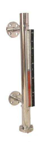
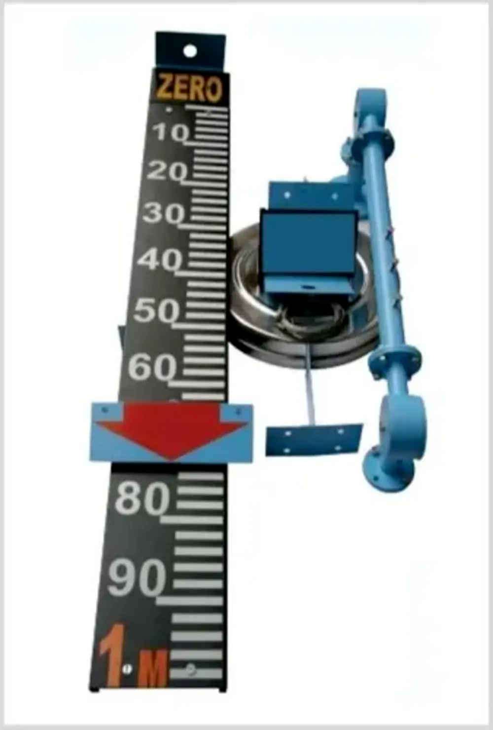 | Level Indicator The Float & Board Level Indicators consists of a float connected to a pointerthrough a rope via a set of pulleys. View product → |
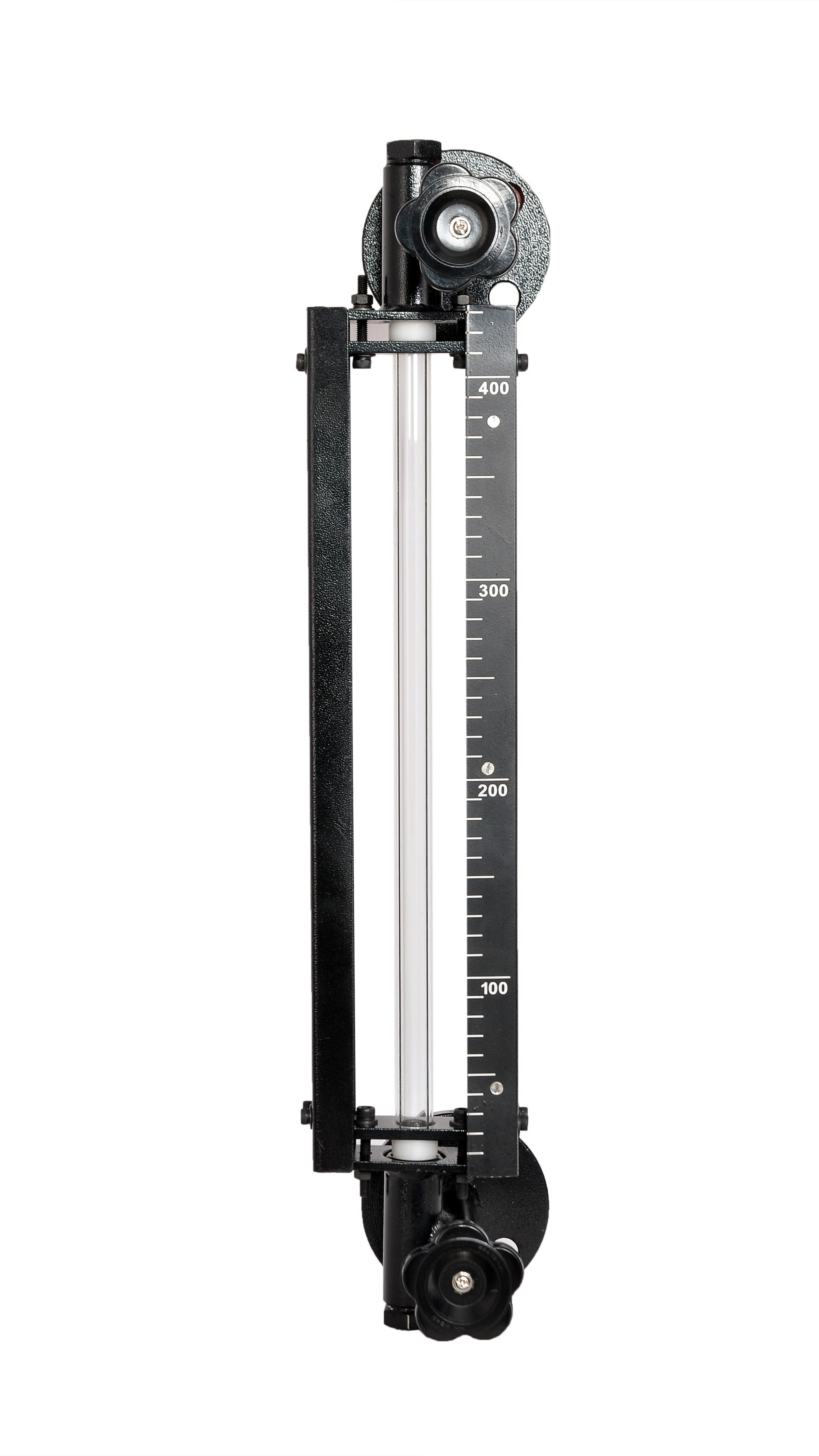
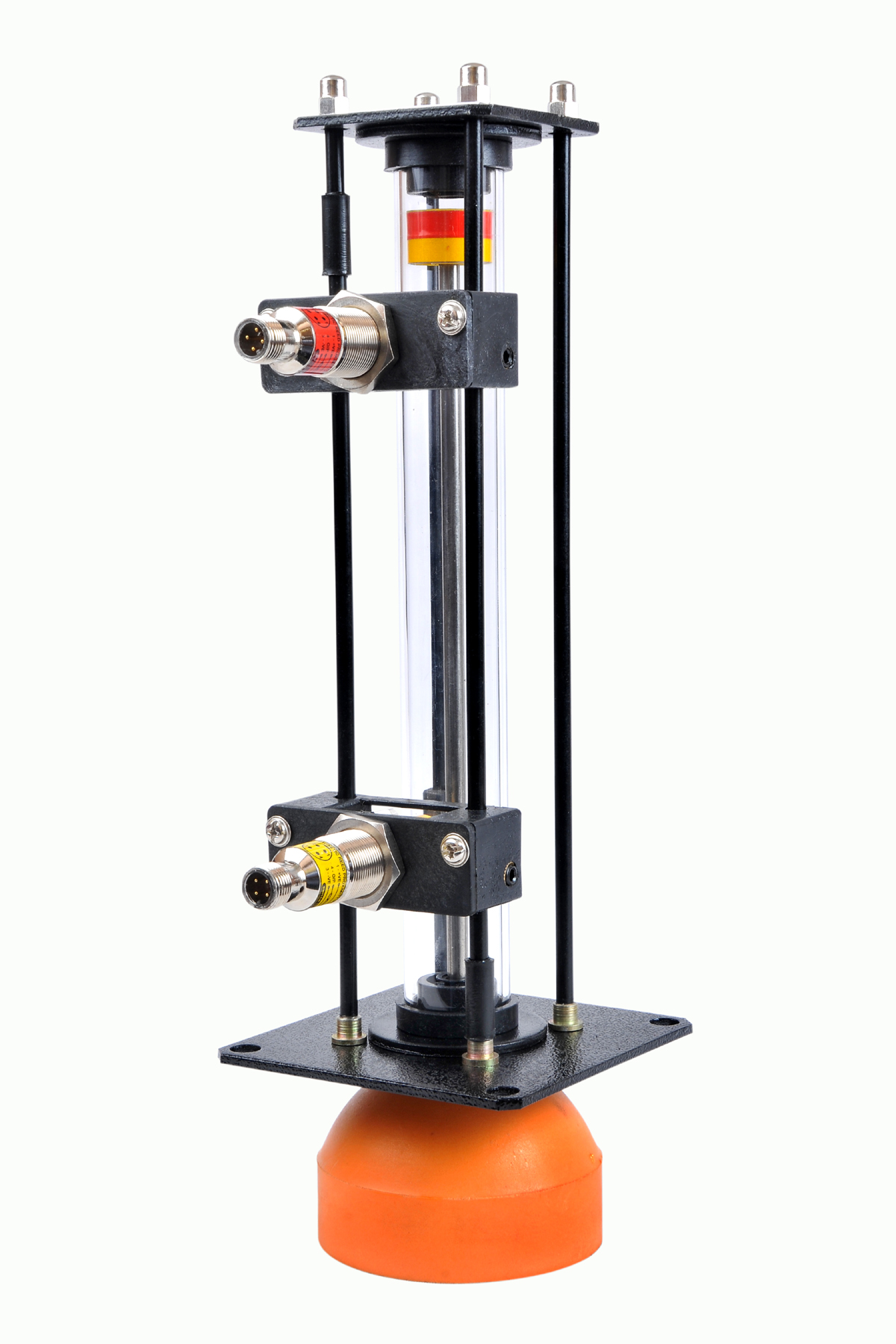 | Level Gauge Oil Level Indicator is designed to indicate the coolant and hydraulic oil level inside the tank with a visual indicator above the tank. View product → |
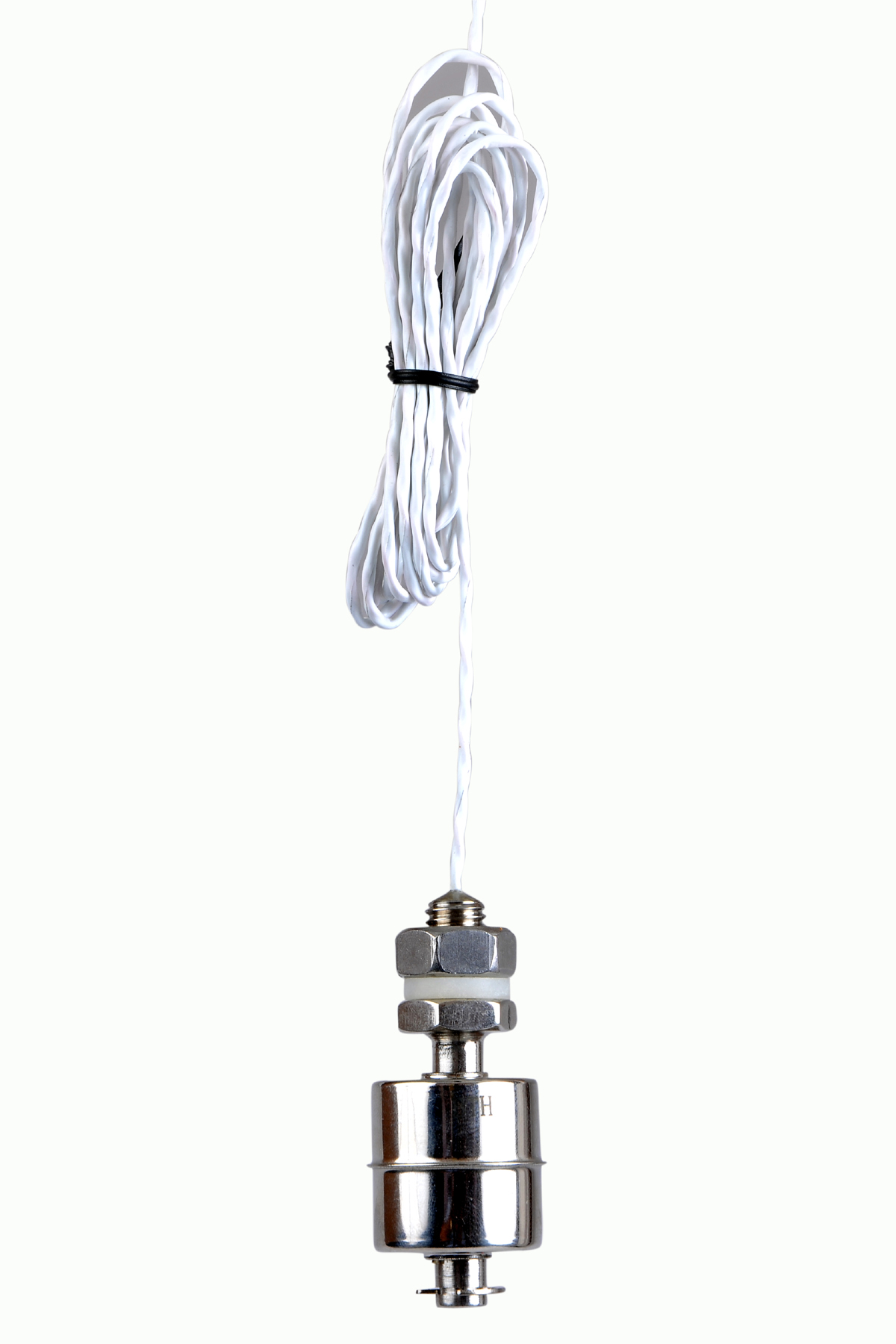 | Level Switch Stainless steel level switch - Miniature Stainless steel Miniature Level Switch is a compact construction, suitable for mounting vertically. View product → |