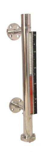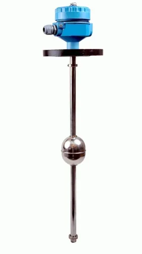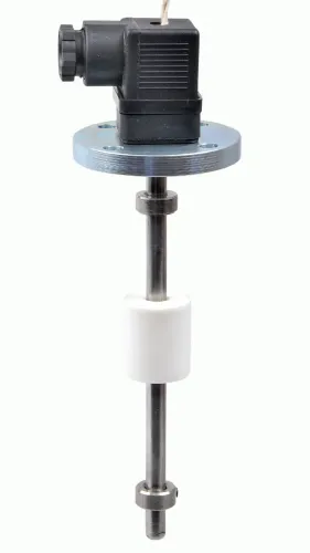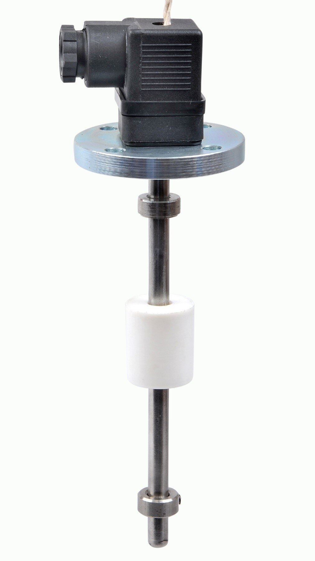
A level transmitter detects where the liquid surface is, converts that physical condition into an electrical value, and sends the result to equipment that can display, regulate or record it. By the end, you will be able to distinguish sensing methods, understand what the output means, and identify installation details that can create a false level reading.
Key takeaways
- Transmitters convert liquid height or surface distance into a control-system signal.
- Hydrostatic devices calculate level from pressure; radar and ultrasonic devices measure distance.
- Install sensors away from turbulence, obstructions, foam, and false signal paths.
- Check the sensor range, output signal, zero point, and tank reference before calibration.
What happens between the liquid surface and the control system?
How does a level transmitter work? It measures a process variable and turns that measurement into a signal for a PLC, panel display, controller or SCADA system. The sensing element detects liquid height or distance to the surface using hydrostatic pressure, radar transit time, ultrasonic transit time, float position or another principle.
The signal chain follows this path:
- The sensor measures the process variable: pressure, distance, displacement or electrical admittance.
- Electronics convert that measurement into the configured lower-range value (LRV) and upper-range value (URV).
- The transmitter sends the result, commonly as a 4–20 mA signal; HART can carry digital configuration and diagnostic data alongside the analog current.
- The receiving system scales, displays, alarms or controls from that value.
A 4 mA signal does not inherently mean an empty tank, and 20 mA does not inherently mean a full tank. The LRV and URV define those meanings against a measurement datum.
A radar transmitter calculates surface distance from its reference point; a differential-pressure transmitter relates liquid head to ΔP = ρgh, so density affects the result.
| Device | What it measures | Output behaviour |
|---|---|---|
| Continuous level transmitter | The changing surface position or a related process variable | A proportional value across the configured range |
| Level switch | Whether liquid has reached a fixed point | Changes state at low, high or high-high level |
A switch can trigger a pump or alarm, but it does not provide the tank’s level between those points.
How do float, capacitance and hydrostatic transmitters determine level?
How does a level transmitter work? A float follows the liquid surface, and its displacement becomes a continuous position signal. Guides keep the float aligned, while mechanical friction can make it stick; turbulence can make the signal hunt or indicate a temporary high or low level.
| Principle | How level is determined | What affects calibration |
|---|---|---|
| Float | Float position tracks the surface and is converted into an electrical signal. | Poor guides, friction, buildup and turbulence distort movement. |
| Capacitance | The probe and tank wall form an electrical measurement whose value changes with the immersed probe length. | Liquid dielectric properties, probe coating and changing product composition alter the reading. |
| Hydrostatic | The transmitter converts pressure head into level using ΔP = ρgh. | Density changes create error when calibration assumes a fixed density. |
For hydrostatic measurement, ρ is liquid density, g is gravity and h is height. A 10% density increase produces roughly a 10% level error under fixed-density calibration.
In an open tank, the low-pressure side references atmosphere; in a closed or pressurised tank, a differential-pressure transmitter compares bottom pressure with vapour-space pressure, largely cancelling common vapour pressure.
A wet-leg reference must remain filled with a known liquid. Trapped gas, condensation in a dry leg, evaporation from a wet leg and unequal temperatures shift zero. Remote-seal capillaries add temperature-related zero shifts as fill-fluid density and capillary behaviour change, especially when capillary lengths or temperatures differ.
How do ultrasonic, radar and guided-wave radar transmitters measure distance?
Non-contact transmitters calculate distance from a reference point to the liquid surface, then subtract that distance from a configured tank height to report level. The reference point is not always the tank roof: it may be the antenna face, nozzle datum or probe connection.
Ultrasonic instruments send an acoustic pulse and measure its round-trip travel time. Gas temperature and composition change sound speed, while foam, vapor, dust, condensation, turbulence, an angled surface or a moving surface can weaken or scatter the echo. The reading may become erratic or freeze on a false echo.
Radar sends electromagnetic waves and measures their transit time; frequency-modulated radar instead calculates distance from the frequency difference between transmitted and returned signals. Configuration must match the antenna datum, nozzle geometry and reference height. A return can come from an agitator, nozzle, heating coil, ladder, buildup or tank bottom instead of the liquid.
Check these points before accepting a radar reading:
- Low-dielectric hydrocarbons produce weaker reflections than water-based liquids, so foam, emulsions and vapor can make the interface ambiguous.
- Approximately 80 GHz radar creates a narrower beam, improving separation from internals and fitting smaller antennas; higher frequency does not remove foam or condensation errors.
- Guided-wave radar directs the signal along a probe, but coating, bridging, an unsupported probe and multiple liquid interfaces can alter the result.
Echo mapping and false-echo suppression help separate the surface return from competing reflections.
How should you install and calibrate a tank level transmitter?
Install and calibrate a tank level transmitter in this sequence:
1. Choose a location away from inlet jets, agitators, ladders and heating coils. Turbulence and obstructions can create unstable readings or false echoes.
2. Check nozzle clearance, antenna or probe insertion length, the transmitter’s measuring dead zone and the usable span. Confirm that the selected nozzle does not place the surface inside the instrument’s blind area.
3. Add a stilling well when the process allows it. It calms turbulence, but size and vent it so the liquid level inside follows the tank level without blockage.
4. Route signal cables separately from motor, heater and other high-power wiring. Bond and ground the transmitter, tank and cable shield exactly as the installation instructions specify.
5. Protect the instrument from vibration, flooding, condensation and mechanical impact. Support remote-seal capillaries without sharp bends or unequal temperature exposure.
6. Enter the tank geometry and measurement reference, then perform echo mapping and false-echo suppression. Exclude nozzle edges, agitator blades, buildup, welds and bottom reflections from the accepted signal.
Calibration must use real reference points, not only the tank’s nominal height. For a DP transmitter, the 0% point can sit above or below the lower pressure tap because of seal elevation; remote seals and wet legs also shift zero.
You can range the transmitter for a partially filled operating band rather than the entire vessel.
| Scaling | Meaning | Use |
|---|---|---|
| Linear | Equal level changes produce equal output changes | Constant-area tanks |
| Non-linear | Output follows the tank’s actual volume curve | Horizontal or irregular vessels |
Set damping or filtering only after testing response. It reduces agitation and pump-induced fluctuation but delays genuine level changes, making it unsuitable as an unexamined setting for an independent high-high trip.
What do the transmitter outputs mean when you connect them to a control system?
Control-system outputs translate level into a value and a control decision. A 4–20 mA signal represents the transmitter’s calibrated lower- and upper-range values: 4 mA equals the configured low point and 20 mA equals the configured high point. Therefore, 4 mA is not inherently empty, and 20 mA is not inherently full.
A 0–10 V output uses voltage instead of current, but long cables, poor grounding and electrical noise can distort the reading. Pulse outputs encode a value in frequency or pulse count; digital communications send measured values, status and configuration data in a defined protocol.
HART adds configuration, diagnostics and a digital process value over a 4–20 mA loop. Do not assume both values behave identically: analog and digital signals can use different scaling, update rates or fault handling.
Commission the signal in this order:
- Verify the measurement datum and empty reference.
- Verify the full reference point and calibrated range.
- Confirm the liquid-density assumption.
- Confirm engineering units.
- Check the configured fault current.
- Confirm which variable the display uses and how the controller scales it.
When comparing suppliers such as Filpro Sensors Pvt Ltd in Delhi, ask for the sensing principle, operating limits, calibration range, installation drawing, output mapping and diagnostic behaviour—not accuracy alone.
Ordinary transmitter accuracy does not create independent overfill protection. An IEC 61511 safety function requires a defined sensor, logic solver, final element, proof-test interval, diagnostics, independence and lifecycle management.
Related products
 | Level Transmitter Float Level Transmitters Are Ideal For Continuous Level Monitoring In Water, Diesel, Chemical And Oils For Accurate Level Measurement. View product → |
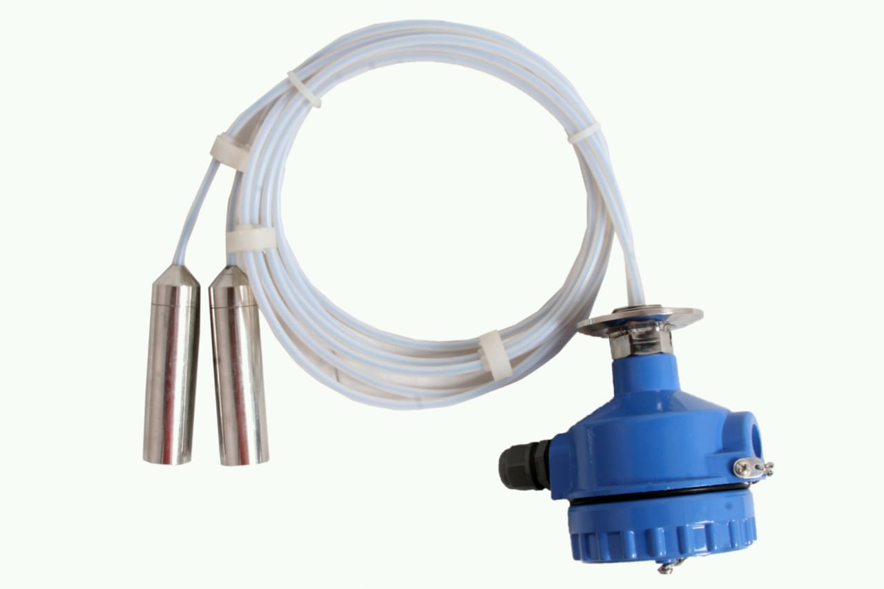 | Level Transmitter can be used for conductive as well as non conductive liquids. View product → |
Frequently asked questions
What happens between the liquid surface and the control system?
A sensing element detects liquid height or the distance to the surface, electronics convert that measurement into an output such as 4–20 mA, and a PLC, display, controller, or SCADA system interprets it as level.
How do float, capacitance, and hydrostatic transmitters determine level?
A float follows the liquid surface, a capacitance probe detects changes in electrical capacitance, and a hydrostatic transmitter calculates level from liquid pressure at a known reference point.
How do ultrasonic, radar, and guided-wave radar transmitters measure distance?
Ultrasonic transmitters time sound pulses, radar transmitters time microwave reflections through the tank space, and guided-wave radar sends the microwave signal along a probe.
How should you install and calibrate a tank level transmitter?
Mount the transmitter where turbulence, foam, obstructions, vapour, and false reflection paths are controlled; then set the measurement range against known empty and full reference points and verify the output.
What do transmitter outputs mean when connected to a control system?
A configured output maps the measured level range to a signal, commonly 4 mA at the lower range value and 20 mA at the upper range value, while digital protocols can carry level, diagnostics, and configuration data.
Related products
 | Level Transmitter Ultrasonic Level Sensor is a non-contact ultrasonic continuous level measurement product based on sound technology. View product → |
 | Level Transmitter Hydrostatic liquid level transducers and transmitters with flush diaphragm is designed fora wide variety of level measurement applications. View product → |
 | Level Sensor Atex approved Float Level Transmitter : Over All Length: 300mm to 5000mm Input: 16V DC to 30V DC Output: 4-20mA / 0-10V DC Resolution: 5mm / 10mm... View product → |
 | Level Switch Filpro offers most reliable, cost effective Side Mounted Level Switch for point level sensing. View product → |