A sensor mounted above a tank can estimate liquid level without a probe, float or pressure connection, but the reading depends on timing, reference dimensions and a clear signal path. By the end, you will know how the echo becomes a level value, how to commission the installation, and when ultrasonic measurement should give way to radar or a contact instrument.
Key takeaways
- Measure level from echo time, gas-space distance and tank reference height.
- Mount the transducer squarely above the liquid and keep the beam clear.
- Check foam, vapour, turbulence, condensation and obstructions when echoes weaken.
- Choose radar, hydrostatic or another technology when ultrasonic conditions are unsuitable.
How an ultrasonic echo becomes a level reading
A non-contact ultrasonic sensor measures the time between sending a sound pulse and receiving its echo from the liquid surface. The result is tank level measurement without contact: the transducer stays above the liquid while the pulse travels through the gas space.
The transmitter converts that time into distance using the speed of sound in the gas space. It then subtracts the measured distance from the configured tank reference height, such as the distance from the sensor face to the tank’s zero level.
- Send an ultrasonic pulse toward the surface.
- Measure the echo’s return time.
- Convert that time to distance, then calculate level from the reference height.
The reading is not volume. A cylindrical tank needs a geometry calculation, while a dished or conical tank needs a strapping or linearization table in the instrument or control system. Without that conversion, the output represents liquid height only.
Gas temperature affects the speed of sound and therefore the distance calculation. Vapour composition, pressure and strong movement in the gas space can also disturb accuracy unless the transmitter compensates for the operating conditions.
Mount the sensor where its acoustic path avoids the filling stream and internal obstructions. A stilling well can shield turbulence, but blocked holes or a plugged chamber can make the displayed level lag behind or differ from the freely moving tank surface.
How to mount, reference and scale the sensor
Make the displayed level match the liquid by defining the instrument’s reference point, usable range and tank geometry before commissioning. A non-contact transmitter measures distance from its antenna face or specified datum, then subtracts that distance from the configured tank reference height. Record every dimension on the installation drawing.
1. Measure the reference height from the antenna datum to the tank’s defined zero level. For a flat-bottom tank, zero may be the floor; for a dished or conical bottom, specify the point where the reported level becomes meaningful.
2. Check the nozzle’s inside diameter, length and orientation against the antenna beam angle. Keep the signal path clear of the wall, agitator, ladder, heating coil, brace, inlet stream and internal pipe.
3. Enter the maximum liquid level below the instrument’s dead zone, then set the configured measurement range between the zero and full reference points. A physical tank capacity is not automatically the transmitter’s 4–20 mA range.
4. Select the tank-shape calculation or load a strapping table when you need volume rather than height. An irregular vessel requires measured height-to-volume points; level alone cannot determine its contents.
5. Configure damping, high and low alarms, echo-failure handling and signal-failure behaviour in the transmitter, PLC or DCS. Confirm that the displayed engineering units and output scaling agree across the complete tank level measurement system.
6. Fill the tank through several known levels and compare the display with a verified reference. Investigate any offset that changes with filling, because turbulence, a false echo or a blocked stilling-well opening can distort the result.
Low-dielectric liquids demand careful antenna and nozzle selection. A stilling well or bypass chamber can stabilise the signal, but inspect it for plugging and sluggish response before accepting its reading.
What weakens the echo and how to troubleshoot it
An ultrasonic reading becomes unstable when the returning sound is weak or arrives from changing surfaces. Foam, heavy vapour, condensation on the transducer, turbulence, a filling stream, and an operating agitator can scatter the pulse.
Gas temperature, composition, pressure and movement also change the speed of sound, so the calculated distance shifts even when the liquid level does not.
- Check the surface during the fault. Note whether filling, foaming, agitation or sudden gas movement begins when the reading wanders.
- Inspect the acoustic path. Remove or account for ladders, braces, pipes and other obstructions, then compare the nozzle length and bore with the sensor’s beam angle.
- Check the sensor face and nozzle for condensation, dust or product buildup. A coated transducer can produce intermittent echoes rather than a clean level signal.
- Review the configured tank reference, measuring range, damping and loss-of-echo response. Compare the transmitter display with the PLC or DCS value; a 4–20 mA signal represents the configured range, not necessarily the tank’s physical capacity.
- If a stilling well or bypass chamber is fitted, inspect its communication holes and chamber for plugging. A blocked path causes sluggish or trapped readings instead of representing the freely moving surface.
Run a controlled test after each correction. If the echo remains unreliable, confirm the sensor’s operating range and application limits before replacing it. Tank level measurement without contact works only when the sound path, gas space and signal configuration remain suitable for the process.
When ultrasonic is the wrong technology
Choose radar, guided-wave radar, hydrostatic, float, or another principle when gas conditions, liquid properties, vessel geometry, or accuracy demands make sound-based measurement unreliable.
| Option | What it means | When it applies |
|---|---|---|
| Radar | Microwave time-of-flight measurement; pulse radar uses round-trip time, while FMCW radar uses frequency difference | Choose it for high temperature, pressure, vapour, gas movement, or changing gas composition. Low-dielectric hydrocarbons need suitable antenna selection, signal processing, nozzle design, and sometimes a stilling well or bypass chamber. |
| Guided-wave radar | Microwave pulses travel along a probe immersed in the tank | Choose it when foam, turbulence, internal obstructions, or a narrow vessel make a free-space signal difficult. The probe must suit the liquid, temperature, pressure, and coating risk. |
| Hydrostatic | A pressure transmitter calculates liquid height from pressure at the tank bottom | Choose it for dirty, opaque, or vapour-filled tanks when density is stable. Changing density, blocked impulse lines, and pressure in a sealed tank create errors. |
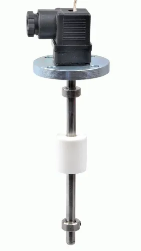
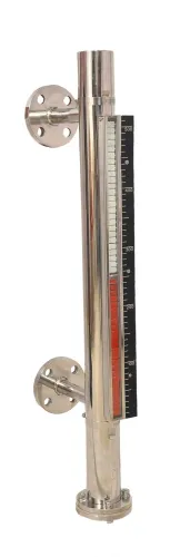
| Float device | A float follows the surface and drives a magnetic, mechanical, or electronic indication | Choose it for simple local indication, independent high-level protection, or sites where power and signal processing are limited. |
| Laser or optical | A narrow light beam measures surface distance | Choose it for a small target or precise surface location in clean, dry service; dust, smoke, condensation, vapour, or a dirty window can stop the return. |
Radar still measures distance, not volume. Your tank level measurement system must apply geometry or a strapping table, scale the 4–20 mA range, and define damping, alarms, diagnostics, and signal-failure action. Choose radar when you need tank level measurement without contact but ultrasonic conditions remain unsuitable.
How to specify the complete level measurement system
Specify the complete tank level measurement system before ordering: record tank reference height, usable range, geometry, liquid name, density, dielectric behaviour, foam condition, vapour composition, temperature, pressure, filling method and agitator operation. Confirm the required measurement—liquid surface, interface below foam, or a conservative high-level value—and keep every setpoint outside the instrument’s blocking distance.
Signal choice determines what the control system can do:
| Signal | Use | Decision to settle |
|---|---|---|
| 4–20 mA | Continuous level or volume | Define the calibrated low and high values; do not assume they equal tank capacity |
| Digital communication | Configuration, diagnostics and supplementary data | Name the protocol and decide whether the PLC or DCS reads the primary value |
| Point alarm output | Independent high, low or overfill action | Define trip levels, reset logic and the safe state on power loss |
Before commissioning, require a loop check at 4, 12 and 20 mA, compare displayed level with a dip measurement or certified reference, test high and low alarms, and simulate signal failure. Verify scaling, damping, tank-volume linearisation, diagnostic handling and the PLC or DCS failure response.
Ask suppliers for the usable range, blocking distance, accuracy under your liquid and vapour conditions, antenna or transducer selection, foam limits, enclosure rating, calibration procedure and configuration backup. Filpro Sensors Pvt Ltd should also be asked to identify which settings reside in the transmitter and which must be programmed in your control system.
Related product
 | Level Transmitter Ultrasonic Level Sensor is a non-contact ultrasonic continuous level measurement product based on sound technology. View product → |
Frequently asked questions
How does an ultrasonic sensor measure tank level without contact?
The sensor sends a sound pulse through the gas space, measures the echo return time, and converts distance to level using the tank reference height.
Where should you mount an ultrasonic level sensor?
Mount it above the liquid with a clear, unobstructed beam, away from inlet flow, internal structures, foam and areas that create turbulence.
What causes a weak ultrasonic level echo?
Foam, vapour, condensation, turbulence, dust, obstructions, poor alignment and an unsuitable measuring range can weaken or distort the echo.
When is ultrasonic level measurement the wrong choice?
Choose another technology when vapour, foam, dust, extreme temperatures, pressure, narrow geometry or difficult surface conditions prevent reliable echoes.