A level switch does not usually power a pump or report a continuous level; it changes an electrical contact when liquid reaches a defined point. By the end, you will be able to trace that contact through a relay, contactor, overload relay, and motor circuit, then choose the switching logic and protections that prevent unsafe operation and rapid cycling.
Key takeaways
- Use the receiving circuit’s voltage; the switch provides an isolated contact.
- Wire the common and normally open or closed terminal to the control circuit.
- Use hysteresis and time delays to stop rapid pump starting and stopping.
- Specify load type, voltage, current, fail-safe action, and switching levels.
What signal does a relay-output level switch actually provide?
A level switch with relay output normally provides an electrically isolated, volt-free contact—not a voltage proportional to liquid level. The receiving circuit supplies its own control voltage through the switch, commonly using an SPDT contact arrangement.
Check the contact rating at the actual AC or DC control voltage; it is separate from the instrument’s supply rating.
The sensing element changes the relay coil’s state at the switching level. Depending on the sensing principle, installation orientation and configuration, the coil energises as level rises and de-energises as level falls, or operates in the reverse sequence. Coil movement transfers the common terminal between the open and closed contacts.
NO and NC describe contact condition, not liquid level:
- NO is open when the relay is in its de-energised reference state.
- NC is closed when the relay is in that same reference state.
- Specify the required contact state on rising level and falling level, with the hysteresis or reset differential.
For filling, configure the logic to start at low level and stop at high level. For draining, reverse that sequence.
Use the relay to command a contactor or motor starter rather than connect a pump directly; starting current, inductive kick and fault current can exceed the switch contacts, while the starter handles motor supply and overload protection.
How do you wire the switch to a pump starter or contactor?
A level switch with relay output usually controls a contactor coil, not the pump motor. The switch’s internal relay changes state at the set level; its volt-free COM contact receives the control voltage, while NO or NC sends that voltage onward according to the required pump action.
1. Confirm the control voltage matches the switch circuit and contactor coil, such as 24 V DC or 230 V AC. Do not assume the switch’s supply rating is its contact rating.
2. Connect one control-supply conductor to the level switch COM terminal. Connect NO for a circuit that must close when the relay energises; connect NC when the circuit must remain closed until the relay changes state. Route the selected terminal to the contactor coil A1.
3. Connect A2 through the control return or neutral, preferably through the starter’s stop circuit and the overload relay’s normally closed auxiliary contact. An overload trip then drops out the contactor instead of leaving the motor commanded on.
4. Wire the motor supply through the contactor’s main poles, then through the thermal or electronic overload relay, and finally to the motor. Bond protective earth separately; never pass it through the contactor.
5. Set the logic for the process. Filling usually starts at low level and stops at high level; draining starts at high level and stops at low level. Use hysteresis or separate thresholds to prevent rapid cycling.
The ratings must match different jobs:
| Rating | Applies to | What to verify |
|---|---|---|
| Switch contact rating | COM, NO or NC circuit | Actual AC/DC voltage, coil current and inductive category |
| Contactor and overload rating | Motor circuit | Motor voltage, full-load current, starting current and fault protection |
A resistive rating does not automatically cover a DC coil or motor load. DC arcs persist longer because there is no natural AC current zero.
How does relay logic choose filling, draining, and alarm actions?
Relay logic chooses actions by assigning separate low- and high-level points to different relay states. For filling, the low-level point starts the pump and the high-level point stops it. For draining, the high-level point starts the pump and the low-level point stops it. Hysteresis prevents rapid cycling at the liquid surface.
| Operation | Start condition | Stop or reset condition |
|---|---|---|
| Filling | Low level reached; run relay latches | High level reached |
| Draining | High level reached; run relay latches | Low level reached |
| High-high alarm | High-high point reached; alarm relay latches | Manual acknowledgement after the level is safe |
A latched run relay keeps the equipment command active after the start point clears, then releases at the stop point. A latched alarm stays active until a defined reset input is received; specify whether power restoration preserves the trip or permits automatic reset.
Define the fail state before selecting NO or NC contacts. A de-energize-to-trip design uses an energized healthy/run permissive, so loss of instrument power or a broken control wire opens the permissive circuit and stops equipment. That arrangement is a system decision, not an automatic property of an NC terminal.
Specify the response to sensor failure separately: stop the pump, close a valve, raise an alarm, or hold the last state. Choose a safe response for the vessel and process. Also state whether power return restarts filling or draining automatically, because an unexpected restart can overflow a tank or run a pump dry.
How do hysteresis and installation details prevent pump cycling?
Hysteresis prevents pump cycling by separating the level that actuates the relay from the level that resets it. A float rises to its actuation position, then must fall to a lower reset position before the contact changes back. Electronic switches use hysteresis, separate setpoints, or a delay.
If that separation is smaller than turbulence, waves, or inlet disturbance, a level switch with relay output can chatter even when it is working correctly.
Prevent false switching during installation:
- Keep the switch away from a direct inlet stream, which can push a float, load a vibrating fork, or create a local high level.
- Use a stilling tube to calm surface movement, but verify that its openings do not clog and that the tube does not change the effective switching level.
- Check nozzle position, insertion length, mounting orientation, dead zone, temperature, pressure, density, and viscosity against the instrument limits.
- Specify the required relay state on rising and falling level; NO or NC alone does not mean high or low level.
| Sensing method | Installation or process limit | Typical false-trip cause |
|---|---|---|
| Conductive | Requires suitable liquid conductivity and electrode contact | Low-conductivity liquid or coating |
| Capacitance | Needs calibration for wall, insulation, dielectric constant, and coating | Product buildup shifts the setpoint |
| Ultrasonic | Requires a clear path and distance outside the dead zone | Foam, vapour, or obstructions |
| Float | Depends on density, viscosity, travel, and orientation | Sticking or turbulent movement |
| Vibrating fork | Needs a clean fork outside continuous process flow | Buildup or flow loading the fork |
What should you specify before connecting the relay output?
Before connecting a level switch with relay output, specify the circuit, process, failure and test conditions in writing.
1. State the switching action on rising and falling level, hysteresis or reset differential, contact form (COM, NO and NC), power-loss fail state, and whether the relay latches or resets automatically.
2. Give the receiving circuit’s actual voltage and load: AC or DC, resistive and inductive current, inrush, and fault level. Do not confuse the switch supply rating with its isolated contact rating.
3. Identify the suppression method for each inductive load. Use a flyback diode or suitable TVS on a DC coil, and an RC snubber or varistor rated for the AC coil; place suppression at the coil.
4. Confirm PLC input type, sourcing or sinking arrangement, common reference, wetting-current requirement and permitted sensor supply. A dry contact often needs an external circuit.
5. Record liquid chemistry, temperature, pressure, turbulence, density, solids and mounting orientation. These conditions determine whether the sensing mechanism will switch reliably.
6. For hazardous areas, verify the complete loop: certification, barrier or isolator, cable, entity parameters, enclosure and installation method.
7. Define the proof test, diagnostic response and reset record, including what operators do after a failed test.
When comparing options, Filpro Sensors Pvt Ltd can help you match the selected switch’s contact limits and configuration to the process, interface and proof-test plan rather than choosing from voltage or thread size alone.
Related products
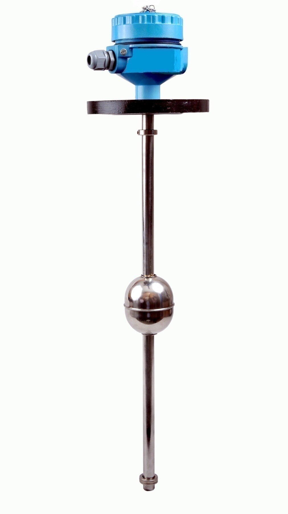
 | Level Switch Filpro offers most reliable, cost effective Side Mounted Level Switch for point level sensing. View product → |
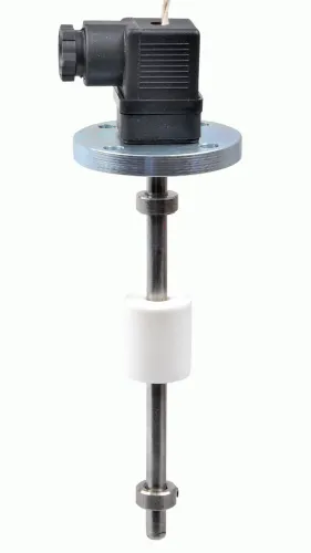
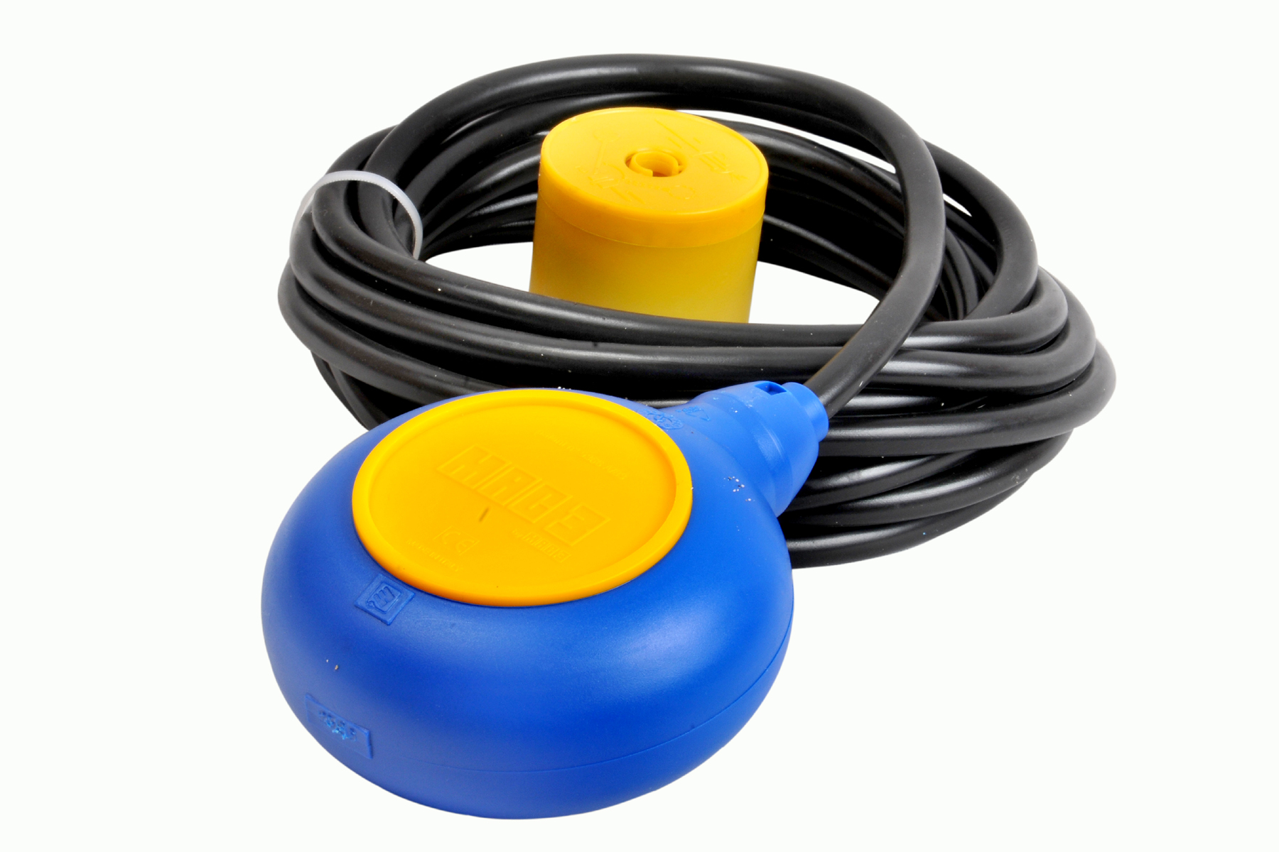 | Level Switch Cable Float Switch is mainly used for the automatic working of small pumps and cellar emptying pumps in liquids a little bit agitated. View product → |
Frequently asked questions
What signal does a relay-output level switch provide?
It provides an electrically isolated, volt-free contact, commonly through an SPDT arrangement. The external control circuit supplies the voltage.
How do you wire a level switch to a pump starter or contactor?
Route the control voltage through the switch’s common terminal and the normally open or normally closed contact, then into the contactor coil circuit. Confirm the coil voltage and contact rating first.
How does relay logic select filling, draining, and alarm actions?
Use the selected contact and switching point to energise or de-energise a pump, valve, or alarm relay. Choose normally energised logic when a loss of power or broken wire must create a fault condition.
How do hysteresis and installation details prevent pump cycling?
Set separate start and stop levels, add a time delay when supported, and install the sensor away from turbulence, inlet flow, and pump-induced waves.
What should you specify before connecting the relay output?
Specify the liquid, tank conditions, mounting position, switch type, switching levels, control voltage, load current, contact arrangement, fail-safe action, and environmental rating.
Related products
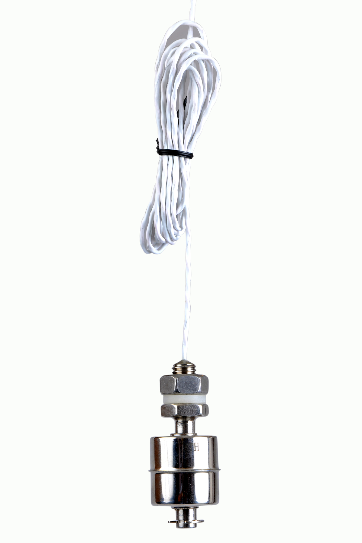 | Level Switch Stainless steel level switch - Miniature Stainless steel Miniature Level Switch is a compact construction, suitable for mounting vertically. View product → |
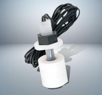 | Level Switch Plastic Miniature Level Switch is available in PP construction with PP Float Switching Voltage: 24V DC Switching current: 0.1A Mounting thread size:... View product → |
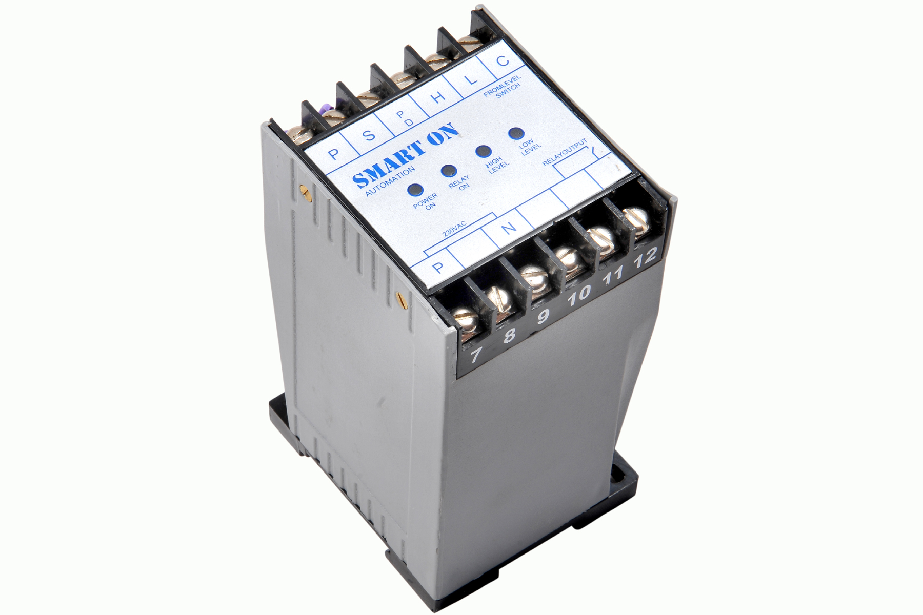 | Controller Filpro Sensors Pvt Ltd manufactures industrial Level Controller (Smart On) to automatically start & stop the pump. View product → |
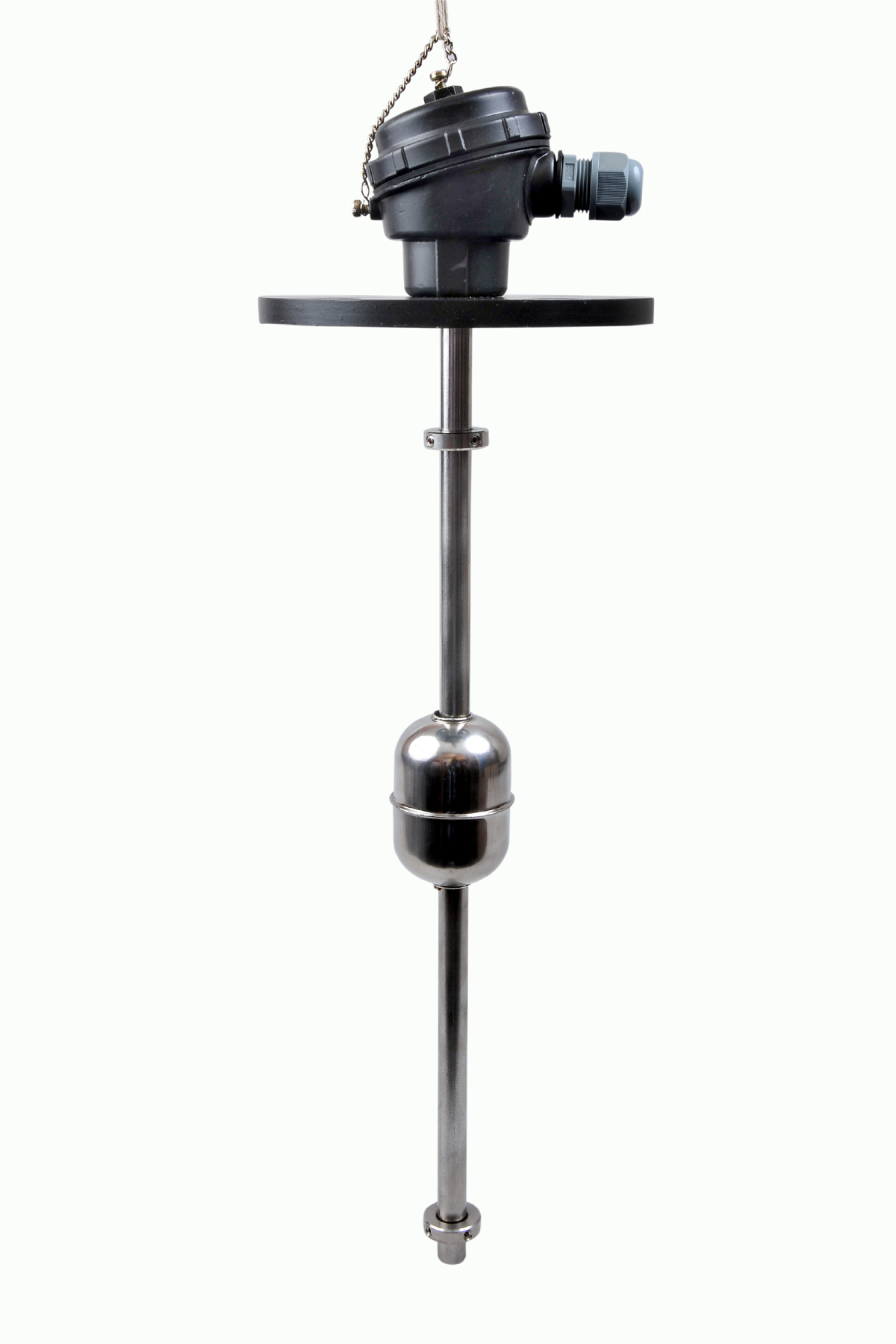 | Level Switch The Magnetic Level Switch consists of the non-abrasive float carrying permanent magnet and non-ferrous stem carrying one. View product → |