The right instrument depends on more than tank height or a quoted accuracy figure. By defining the tank, liquid, operating conditions, measurement span and control-system requirements first, you can eliminate unsuitable technologies before installation and specify a system that remains reliable in service.
Key takeaways
- Record tank geometry, liquid properties and the control objective first.
- Choose radar, ultrasonic, hydrostatic or other technology from process conditions.
- Define usable span, accuracy, repeatability and response time before requesting quotes.
- Verify signal, mounting, materials and protection across the full operating envelope.
Start with the tank, liquid and control objective
Choose continuous tank level measurement after recording the tank, liquid and control objective. Measure tank height, nozzle locations, internal obstructions, roof shape and available installation space. State whether the vessel is open, vented, sealed or pressurised; a closed tank requires vapor-space pressure data as well as bottom pressure.
Collect these operating details:
- Liquid density and its operating range, viscosity, conductivity, dielectric constant, temperature and pressure
- Foam, vapour, condensation, turbulence, sludge, emulsion layers and solids
- Required accuracy, response time, alarm points, control range and whether you need level, volume or mass
- Whether the instrument controls the process or provides a separate high-high overfill shutdown
- Maintenance access, cleaning method, hazardous-area classification and power or signal requirements
| Information | Why it changes the choice |
|---|---|
| Tank pressure and vapour space | Hydrostatic measurement follows ΔP = ρgH. On a closed tank, use bottom and vapor-space pressure; a gauge transmitter at the bottom will mistake vapor-pressure changes for level. |
| Density stability | A water-ranged transmitter over-reads a lower-density liquid and under-reads a higher-density liquid unless you compensate or recalibrate. |
| Surface and vapour conditions | Radar handles vapour composition, temperature and pressure better than ultrasonic, but foam, turbulence, obstructions, poor nozzles and weak dielectric reflection can lose the echo. |
| Mechanical and interface conditions | A displacer depends on buoyancy and immersion; density changes, emulsion, friction or cage plugging cause disagreement. A stilling well reduces turbulence, but plugging or poor venting creates a stable wrong reading. |
| Safety function | Do not count the control transmitter as independent overfill protection if the shutdown shares its sensor, impulse lines, power supply or failure modes. Define IEC 61511 proof-test independence. |
Match the measurement technology to the process conditions
Choose the technology that tolerates your liquid and tank conditions, not the one with the simplest brochure specification. For continuous tank level measurement, compare these real-service trade-offs:
| Option | Best fit | Main failure or limitation |
|---|---|---|
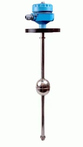
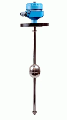
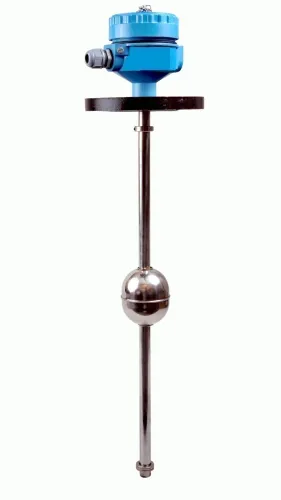
| Float | Clean, calm liquids in tanks where a mechanical device can move freely | Sludge, viscous product, buildup, guide friction or a restricted float causes a sticking reading |
| Ultrasonic | Open or vented tanks with a clear surface, moderate temperature and little foam | Foam, vapour, condensation, turbulence, obstructions and a narrow nozzle weaken or misplace the echo |
| Hydrostatic | Open or vented tanks holding liquids with stable density | The reading follows ΔP = ρgH; a water-calibrated transmitter over-reads low-density liquid and under-reads high-density liquid |
| Capacitance | Liquids with a stable dielectric constant and a probe that stays clean | Product coating or a changing dielectric constant shifts calibration and creates drift |
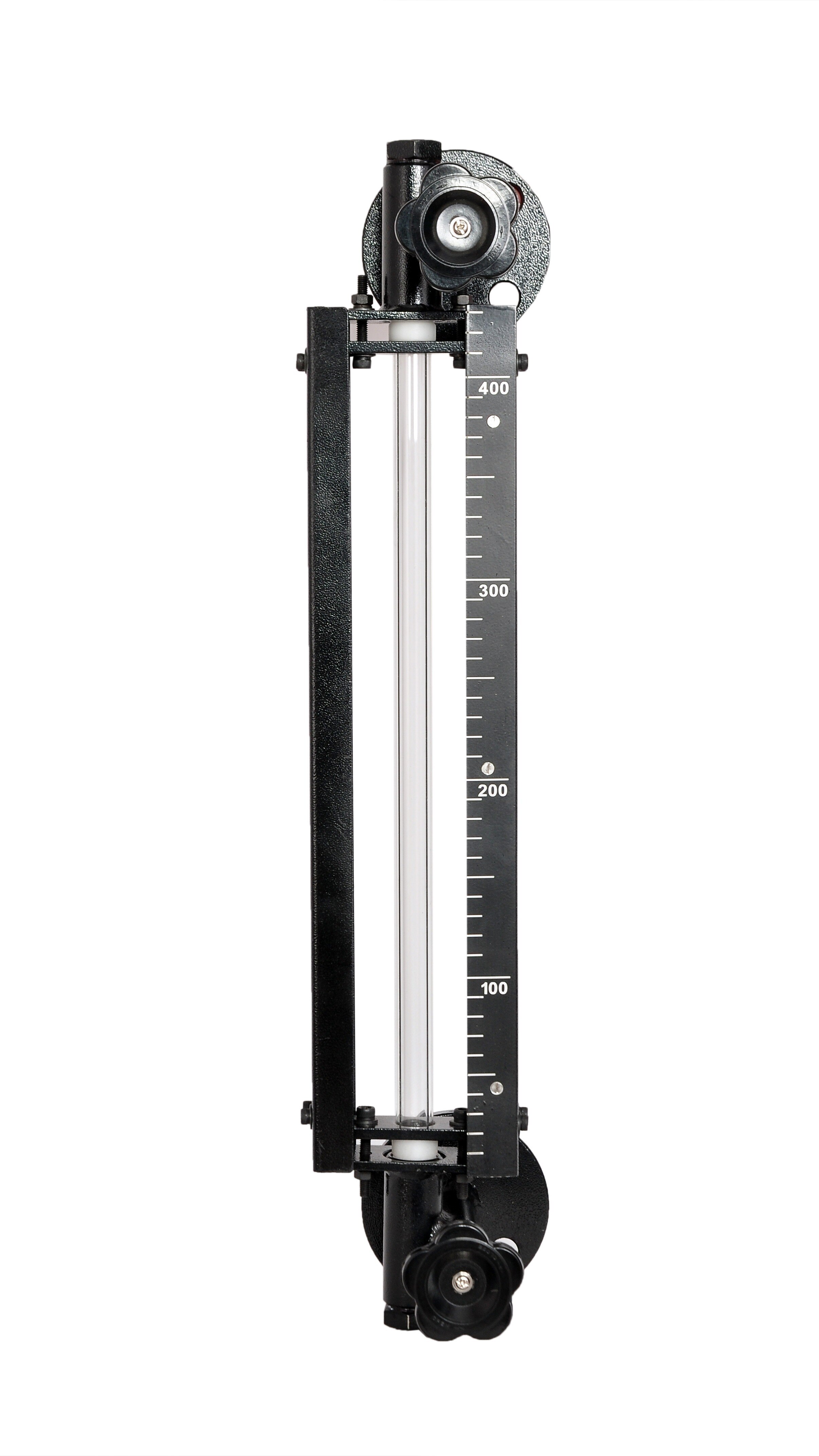
| Visual float-and-board | Simple local indication where power, automation and high accuracy are unnecessary | It does not provide a remote control signal, and the float mechanism can foul or stick |
| Radar | Closed or open tanks exposed to vapour, temperature or pressure variation | Foam, turbulence, internal obstructions, poor nozzle geometry and weak surface reflection cause false echoes or signal loss |
| Guided-wave radar | Narrow vessels, bypass chambers or a concentrated measurement zone | Viscous product, coating, bridging or interface changes can disturb the probe reflection |
In a closed tank, hydrostatic measurement needs both bottom pressure and vapour-space pressure; bottom gauge pressure alone mistakes vapour-pressure changes for level. A stilling well can steady radar or ultrasonic readings, but a blocked or poorly vented well gives stable, wrong data. Size the range for operating extremes plus credible overrange, not tank height alone.
Calculate the usable span and define performance properly
Set the measuring range from the lowest and highest credible levels, not from the tank’s nominal height. Calculate:
- Lower endpoint: the minimum operating level, including any required emptying margin.
- Upper endpoint: the maximum normal operating level.
- Overrange allowance: the highest credible level during filling, foam, pressure excursions or vacuum conditions.
Choose a span that contains all three conditions without saturation. Excess span reduces resolution when uncertainty is expressed as a percentage of span; an undersized span clips the signal when the process exceeds the upper endpoint.
| Metric | Meaning | What to verify |
|---|---|---|
| Resolution | Smallest level change the instrument can distinguish | Compare it with the control deadband and required batch increment |
| Accuracy | Closeness of the reading to the actual level | Check the stated reference conditions and total tank error |
| Repeatability | Agreement among repeated readings at the same level and conditions | Look for drift, hysteresis and mechanical friction |
| Calibration error | Difference between applied reference levels and indicated output during calibration | Record zero error, span error and the result after adjustment |
A transmitter’s accuracy figure does not equal inventory accuracy. Tank geometry, nozzle elevation, dead volume and level-to-volume conversion can dominate the final error. For hydrostatic continuous tank level measurement, density changes the result through ΔP = ρgH; a closed tank also requires vapor-space pressure compensation.
Keep overfill shutdown independent when the safety function claims separate risk reduction.
Specify the signal, installation and protection requirements
Specify the control-system interface before choosing the sensor. Confirm that the PLC, DCS or safety system accepts a 4–20 mA level transmitter, provides the required loop power and load resistance, and interprets upscale and downscale fault currents correctly. Record the tank level transmitter output, alarm thresholds and cable requirements.
HART level measurement adds configuration and diagnostic data but does not replace a compatible analogue input.
Record these requirements in the purchase specification:
- For a closed tank, use a differential-pressure transmitter with connections for both liquid-side pressure and vapour-space pressure. A bottom-only gauge-pressure transmitter will convert vapour-pressure changes into false level changes.
- For an open or vented tank, state the liquid density and its operating range. Hydrostatic output follows ΔP = ρgH, so density changes require compensation or recalibration.
- Specify wetted materials, diaphragm and seal compatibility, maximum pressure, vacuum rating, process and ambient temperature limits, and the consequence of a failed process connection.
- Name the hazardous-area certification, such as ATEX or IECEx, plus the required enclosure rating and cable-entry arrangement.
- Check nozzle size, insertion length, grounding and access for maintenance. Foam, turbulence, obstructions and poor nozzle geometry can defeat a radar reflection.
Do not claim an independent overfill layer from the continuous transmitter alone. An IEC 61511-based high-high shutdown needs independence and proof-test performance; sharing its sensor, impulse lines or power supply with the control loop can remove the intended risk reduction.
When reviewing a proposal from Filpro Sensors Pvt Ltd, request these interface, certification and independence details in writing.
Related products
 | Level Transmitter Float Level Transmitters Are Ideal For Continuous Level Monitoring In Water, Diesel, Chemical And Oils For Accurate Level Measurement. View product → |
 | Level Transmitter Ultrasonic Level Sensor is a non-contact ultrasonic continuous level measurement product based on sound technology. View product → |
Validate the choice against the real operating envelope
Before approval, test the instrument across the real operating envelope and document whether its error meets the decision’s risk: inventory, batching, pump protection or process control. Do not approve it from the catalogue accuracy alone.
1. Record the minimum and maximum level, credible overrange, required response time, tank geometry, nozzle dimensions, dead volume and conversion from level to volume. Include temperature, pressure, vacuum, agitation, foam, vapour, condensation and coating conditions.
2. Test the actual liquid at its minimum and maximum dielectric constant or density. For hydrostatic continuous tank level measurement, verify density compensation: ΔP = ρgH, so a water-calibrated transmitter misreads a liquid with a different density.
In a closed tank, connect and test both bottom pressure and vapour-space pressure; a bottom gauge transmitter will mistake vapour-pressure changes for level.
3. Run filling, emptying, foaming, agitation and upset-condition trials. Record indicated level, reference level, response time, signal stability, loss of echo or saturation, and recovery after the upset. Check the full tank-level measurement accuracy after including dished ends, tilted installation, thermal expansion and level-to-volume calculation error.
4. Document calibration points, acceptance limits, alarm settings, environmental conditions, test equipment and results. Confirm that the selected span covers operating levels and overrange without wasting resolution.
5. For high-high overfill shutdown, verify an independent protection layer under the IEC 61511 safety lifecycle. A shared sensor, impulse line, power supply or failure mode does not provide independent risk reduction; record proof-test interval, coverage and bypass controls separately from the control loop.
Frequently asked questions
What information should you collect before choosing continuous tank level measurement?
Record tank height, nozzle locations, roof shape, internal obstructions, installation space, vessel pressure and the control objective. Also document liquid density, temperature, vapour, foam, solids and corrosive properties.
How do you match level measurement technology to process conditions?
Compare the liquid and vessel conditions with each technology’s limits. Radar suits many vapour and pressure conditions, ultrasonic needs a clear acoustic path, and hydrostatic measurement depends on liquid density and pressure conditions.
How do you define the usable measurement span?
Set the highest and lowest operating levels, then account for dead zones, nozzle position, tank geometry and the required alarm or control margins. Specify accuracy, repeatability, resolution and response time across that span.
What installation and signal requirements should you specify?
State the output, such as 4–20 mA or a digital protocol, power supply, connection size, mounting position, wetted materials, enclosure protection and hazardous-area requirements.
How do you validate a level measurement choice?
Check the proposed instrument against the real minimum and maximum levels, temperature, pressure, density, foam, vapour, agitation, cleaning cycle and environmental conditions.
Related products
 | Level Sensor Atex approved Float Level Transmitter : Over All Length: 300mm to 5000mm Input: 16V DC to 30V DC Output: 4-20mA / 0-10V DC Resolution: 5mm / 10mm... View product → |
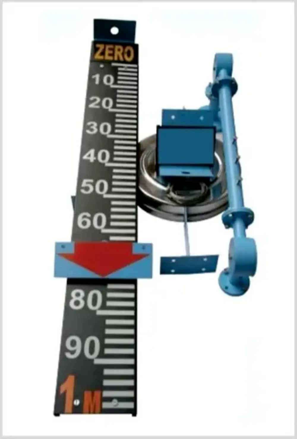 | Level Indicator The Float & Board Level Indicators consists of a float connected to a pointerthrough a rope via a set of pulleys. View product → |
 | Level Transmitter Hydrostatic liquid level transducers and transmitters with flush diaphragm is designed fora wide variety of level measurement applications. View product → |
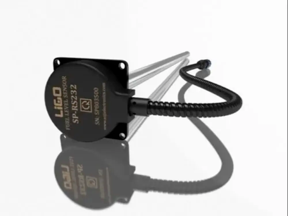 | Level Sensor Ligo fuel sensor for monitoring Diesel and Petrol level in vehicle fuel tanks and DG sets. View product → |